
Phenol pollutant removal system and method based on moving bed biofilm reactor

A moving bed biofilm and reactor technology, applied in the field of water treatment, can solve problems such as continuous consumption, and achieve the effect of ensuring sustainability and realizing in-situ recycling and regeneration.

Inactive Publication Date: 2019-03-29
DALIAN UNIV OF TECH
View PDF3 Cites 3 Cited by
  • Summary
  • Abstract
  • Description
  • Claims
  • Application Information

AI Technical Summary

Problems solved by technology

However, in this field, there are still some problems in the application of bio-manganese oxides. For example, the bio-manganese oxides in the reaction system are continuously consumed and thus need to be continuously replenished.

Method used


Image

  • Phenol pollutant removal system and method based on moving bed biofilm reactor
  • Phenol pollutant removal system and method based on moving bed biofilm reactor
  • Phenol pollutant removal system and method based on moving bed biofilm reactor

Examples


Embodiment 1

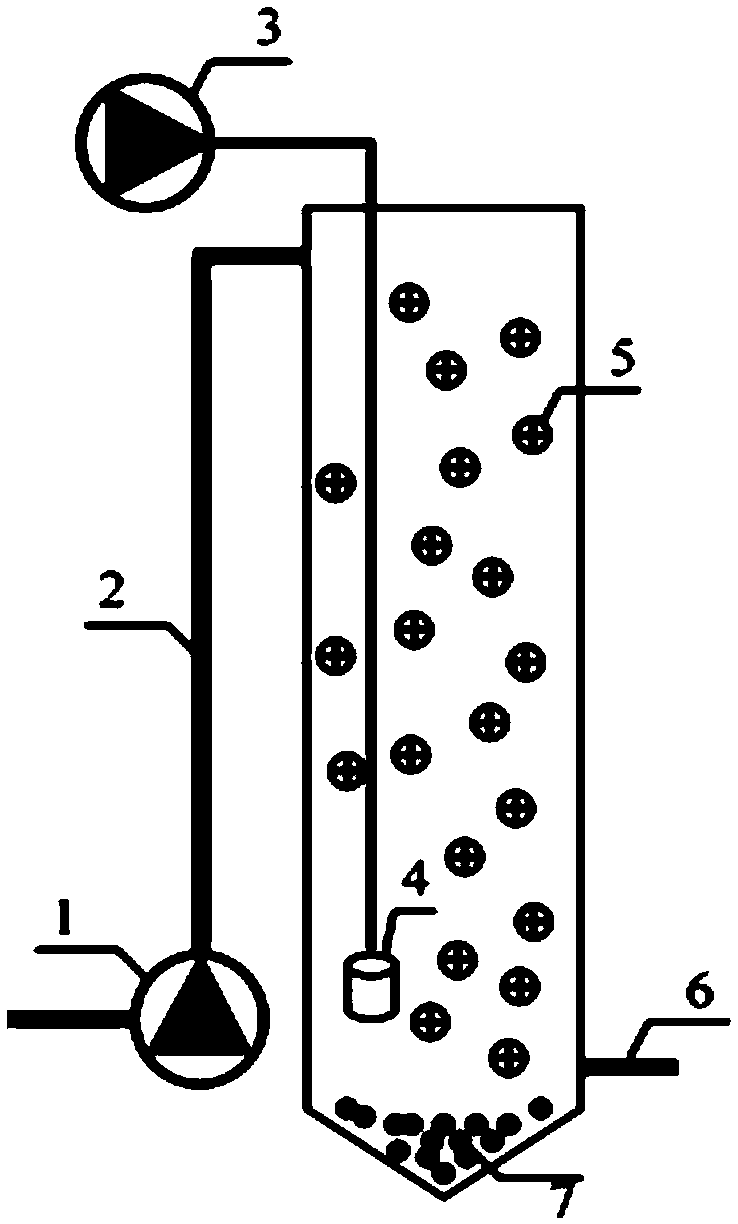
[0045] This embodiment discloses a phenolic pollutant removal system based on a moving bed biofilm reactor, and its structure is as attached figure 1 As shown, it includes a reactor, a water inlet pump 1, an aeration pump 3, and an aeration head 4. The water inlet at the upper end of the reactor is in communication with the water inlet pump 1 through a water inlet pipe 2, and a biofilm filler 5 is provided in the reactor. , The bottom of the reactor is provided with a biological manganese oxide 7, and an aeration head is provided in the reactor above the biological manganese oxide, and the aeration head is in communication with an aeration pump set above the reactor through a pipeline A water outlet is provided on the side wall of the reactor above the biological manganese oxide, and the water outlet is in communication with the water outlet pipe 6. The moving bed biofilm reactor can realize in-situ generation and recycling of biomanganese oxide.

[0046] The steps of the phenol...

Embodiment 2

[0071] This example discloses a phenolic pollutant removal system based on a moving bed biofilm reactor. Based on Example 1, we set the hydraulic residence time of the entire reactor to 24h in Example 2.

[0072] 1. Wastewater treatment parameters

[0073] The wastewater is treated with simulated wastewater prepared in the laboratory. The main water quality indicators: COD 1500mg / L, NH 4 + -N90mg / L, phenol concentration 600mg / L, p-chlorophenol concentration 30mg / L.

[0074] 2. Wastewater treatment stage

[0075] The reactor was operated in sequential batch mode, and the hydraulic retention time was set to 24h. The other conditions are consistent with Example 1.

[0076] 3. The effect of reactor operation

[0077] After testing, the change of hydraulic retention time significantly affected the phenol removal performance of the combined system. Monitor the concentration of phenol in the effluent of the reactor (12h, 24h) and the concentration of p-chlorophenol in the effluent (6h, 12h) b...


PUM


Abstract

The invention provides a phenol pollutant removal system and method based on a moving bed biofilm reactor. The phenol pollutant removal system based on the moving bed biofilm reactor comprises a reactor, a water inlet pump, an aeration pump and an aeration head; a water inlet at the upper end of the reactor communicates with the water inlet pump; the reactor is internally provided with biologicalmembrane filler; the bottom of the reactor is provided with a biological manganese oxide; the aeration head is arranged in the reactor and above the biological manganese oxide, wherein the aeration head communicates with the aeration pump arranged above the reactor through a pipeline; and a water outlet is formed in the side wall, above the biological manganese oxide, of the reactor. According tothe phenol pollutant removal system based on the moving bed biofilm reactor, the biological manganese oxide can be generated in situ, and combined catalysis of microorganisms / the biological manganeseoxide on phenolic pollutants is realized.

Description

Technical field [0001] The invention relates to water treatment technology, in particular to a phenolic pollutant removal system and method based on a moving bed biofilm reactor. Background technique [0002] In recent years, reports and researches on phenolic pollutants in industrial wastewater have become more and more extensive. How to effectively remove phenolic pollutants contained in industrial wastewater has become a hot research topic at home and abroad. Phenolic pollutants, as a class of pollutants that are highly toxic to humans and the environment, are often by-products produced in industrial production processes, and cover many areas, including drugs, personal care products, steroid hormones, chemical raw materials, and pesticides. Insect agents and so on. With the rapid development of petrochemical, oil refining, plastics, pharmaceutical and other industries, the types and quantities of phenol-containing wastewater discharged are also increasing, posing a huge threa...

Claims


Application Information

Patent Timeline
Patent Type & Authority Applications(China)
IPC IPC(8): C02F3/34C02F3/00B01J23/34
CPCB01J23/34C02F3/00C02F3/34
Inventor 周豪王国晨杨重潘海霞占敬敬柳丽芬
Owner DALIAN UNIV OF TECH
Learn More