A method for predicting the milling force of end face milling cutter combined with SVM

A prediction method and face milling cutter technology, applied in the direction of instrumentation, calculation, design optimization/simulation, etc., can solve the problems of large cutting force error, decreased cutting force calculation accuracy, long calculation time, etc., to improve efficiency and shorten simulation time , the effect of reducing the amount of calculation

Active Publication Date: 2019-03-29
XIAMEN UNIV +1
View PDF5 Cites 5 Cited by
  • Summary
  • Abstract
  • Description
  • Claims
  • Application Information

AI Technical Summary

Problems solved by technology

[0002] There are usually three traditional cutting force prediction methods: 1. empirical formula, 2. cutting force coefficient identification (Engin S, Altintas Y. Mechanics and dynamics of general milling cutters.: Part II: inserted cutters [J]. International Journal of Machine Tools&Manufacture,2001,41(15):2195-2212; Yao Q, Wu B, Luo M, et al.On-line cutting force coefficient identification for bull-end milling process with vibration[J].Measurement,2018,125.( 2)), 3. Overall tool cutting force finite element simulation (Tapoglou N, Antoniadis A.3-Dimensional kinematics simulation of face milling[J].Measurement,2012,45(6):1396-1405.), cutting force experience The formula can only predict the peak value or mean value of the cutting force, but cannot obtain the accurate cutting force time history curve. The cutting force coefficient identification method can identify the linear model or the simple exponential model coefficient based on the experimental data, and use the model to calculate the cutting force of the micro-element of the blade. Describe, and then solve the cutting force of each micro-element according to the motion equation of each micro-element, and finally superimpose and solve the overall cutting force of the tool. This method is a common method for solving the time-history curve of cutting force
However, because the method is based on experimental data, the influence of factors such as machine tool spindle deformation and vibration is often recovered, which leads to a decrease in the accuracy of cutting force calculations, and the use of simple linear models or exponential models to describe the micro-element cutting force of the blade has a large error
However, the finite element simulation of the cutting force of the overall tool is difficult to apply to the simulation of the cutting force of the large-diameter multi-blade tool. This kind of tool has a large amount of mesh, a large amount of calculation, and a long calculation time. It is difficult to guarantee the simulation accuracy of the large-diameter multi-blade cutting force.

Method used


Image

  • A method for predicting the milling force of end face milling cutter combined with SVM
  • A method for predicting the milling force of end face milling cutter combined with SVM
  • A method for predicting the milling force of end face milling cutter combined with SVM

Examples


Embodiment Construction

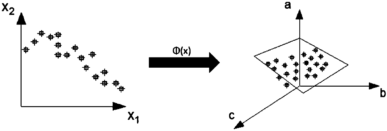
[0026] The technical difficulties of the present invention mainly lie in the geometric modeling of the blade finite element model and the solution of the cutting force model and the tool tip kinematics model fitted by the hybrid kernel function SVM method. The following embodiments will further illustrate the present invention in conjunction with the accompanying drawings. The specific measures are as follows:

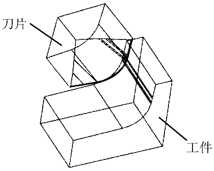
[0027] 1) Design 100 sets of simulation parameters with different depths of cut and different radial back cuts (5 sets of different parameters for depth of cut and radial depth of cut), and establish a geometric model. The geometric model is as follows: figure 1 As shown, the position of the cutting edge of the insert needs to be rounded, and the insert only takes the part of the tip that is in contact with the workpiece, reducing the number of grids and improving the accuracy of the grid, so that the grid can combine the shape of the tiny structure on the blade. The l...


PUM


Abstract

The invention relates to a method for predicting the milling force of an end face milling cutter combined with SVM, which relates to an ultra-precision machining technology. The simulation parametersof different cutting depth and different radial feed back are designed, and the geometric model is established. The round corners are arranged at the cutting edge position of the insert, and the insert only takes the tip part which is in contact with the workpiece, so that the mesh can combine the shape of the micro-structure on the insert. After getting the simulation value, the mixed kernel function SVM algorithm is used to fit the simulation value. the tool tip kinematics model is computed. According to the kinematics model, At that current phase angle, the cut forces of each insert are calculated by substituting the cutting force model into the cutting force model. The cutting forces are divided into three directions: axial force, radial force and tangential force, which are convertedinto tool axial force Fz, feed direction force Fy and perpendicular feed direction force Fx, and the cutting forces are directly superposed and solved.

Description

technical field [0001] The invention relates to ultra-precision machining technology, in particular to a method for predicting the milling force of an end mill combined with SVM, which can be used in the calculation of the vibration of the main shaft and the calculation of the roughness of the machined surface. Background technique [0002] There are usually three traditional cutting force prediction methods: 1. empirical formula, 2. cutting force coefficient identification (Engin S, Altintas Y. Mechanics and dynamics of general milling cutters.: Part II: inserted cutters [J]. International Journal of Machine Tools&Manufacture,2001,41(15):2195-2212; Yao Q, Wu B, Luo M, et al.On-line cutting force coefficient identification for bull-end milling process with vibration[J].Measurement,2018,125.( 2)), 3. Overall tool cutting force finite element simulation (Tapoglou N, Antoniadis A.3-Dimensional kinematics simulation of face milling[J].Measurement,2012,45(6):1396-1405.), cutting ...

Claims


Application Information

Patent Timeline
Patent Type & Authority Applications(China)
IPC IPC(8): G06F17/50
CPCG06F2119/06G06F30/23
Inventor 王建军姚斌宋世毅蔡思捷陈彬强蔡志钦黄景山杨小勇王裕喆刘红霞李晨硕尹晨旭
Owner XIAMEN UNIV
Why Eureka
Try Eureka