A radiator with raised fins on the surface

A radiator, radial technology, used in cooling/ventilation/heating transformation, electrical components, electrical equipment structural parts, etc., can solve the problems of large end spacing, limited number of fins, large flow resistance, etc., to achieve flow speed Increase, improve the cooling effect, strengthen the effect of disturbance

Active Publication Date: 2020-07-10
HUAZHONG UNIV OF SCI & TECH
View PDF10 Cites 0 Cited by
  • Summary
  • Abstract
  • Description
  • Claims
  • Application Information

AI Technical Summary

Problems solved by technology

[0004] Although the radiators of high-power electronic components have been partially improved and optimized in the prior art, the traditional straight-fin radial radiators for CPU cooling still have the following disadvantages: due to the limited radius of the solid cylinder, the radius of the circumference of the fin root Smaller than the radius of the fin end circumference, the number of fins of a radiator with a certain rib thickness is limited, so the area participating in convective heat transfer is limited; the fins near the cylindrical end are closely arranged, and the flow resistance is large, while the distance between the ends becomes larger, and the flow The resistance is small, because the flow area of ​​the air changes from small to large when participating in the heat exchange process, coupled with the centrifugal force of the fan rotation, it will preferentially flow out from the middle and upper part of the flow channel at the end of the fin, resulting in less airflow that is actually close to the heat source surface to participate in heat exchange. This means that heat transfer is less effective at the bottom of the fins and near the ends

Method used


Image

  • A radiator with raised fins on the surface
  • A radiator with raised fins on the surface
  • A radiator with raised fins on the surface

Examples


Embodiment Construction

[0026] In order to make the object, technical solution and advantages of the present invention clearer, the present invention will be further described in detail below in conjunction with the accompanying drawings and embodiments. It should be understood that the specific embodiments described here are only used to explain the present invention, not to limit the present invention. In addition, the technical features involved in the various embodiments of the present invention described below can be combined with each other as long as they do not constitute a conflict with each other.

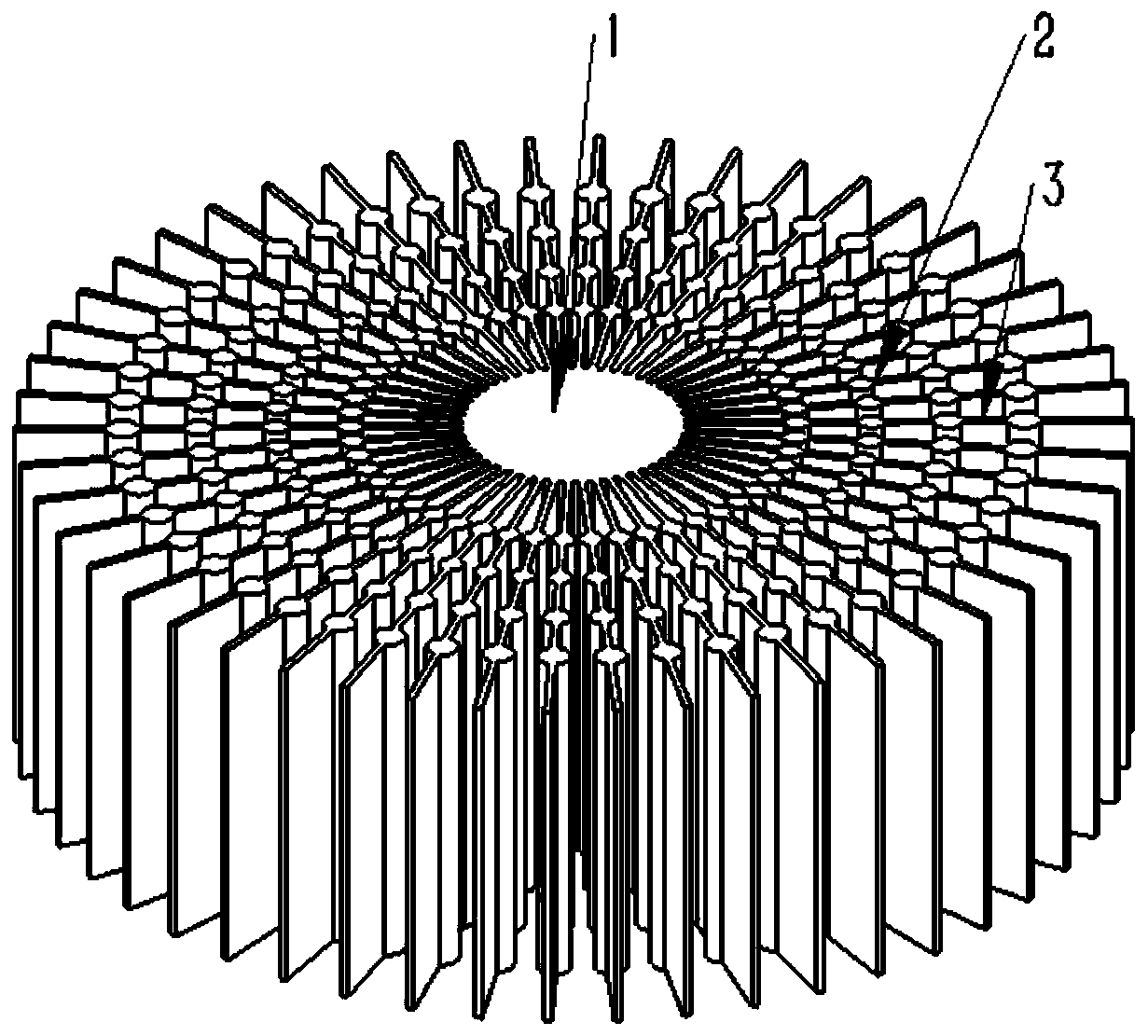
[0027] Such as figure 1 As shown, the present invention provides a radiator with protrusions on the surface of the radial fins, which is characterized in that the radiator includes a solid cylinder 1, ribs 3 and protrusions 2, wherein:

[0028] The bottom surface of the solid cylinder 1 is close to the electronic device (such as high-power LED, computer CPU) as a heat source, and the temperatur...


PUM


Abstract

The invention belongs to the field of heat dissipation of electronic devices and discloses a heat dissipater having protrusions on the surfaces of radial ribs. The heat dissipater comprises a solid cylinder, protrusions and ribs, wherein the bottom of the solid cylinder is close to an electronic device used as a heat source, and reduces the temperature of the heat source by means of heat conduction. The side of the solid cylinder is connected with a plurality of radial ribs. Gaps between every two adjacent ribs form airflow paths. The air takes the heat of the heat dissipater away by heat convection. The protrusions are in cylindrical shapes and vertically disposed on the ribs, have an eight equal to that of the ribs and are used for increasing the heat exchange area and enhancing the heatconvection effect of the air. The cylindrical protrusions are disposed on the ribs of the heat dissipater to increase the convection heat exchange area, increase the air flow speed and enhance the convection heat transfer effect. The presence of the protrusions enhances the disturbance of the air flow and is also beneficial to improving the heat dissipation effect.

Description

technical field [0001] The invention belongs to the field of heat dissipation of electronic devices, and more specifically relates to a radiator with protrusions on the surface of radial fins. Background technique [0002] The radial fin radiator is a heat dissipation device composed of a solid cylinder and multiple radial fins. It is mainly used for heat dissipation of high-power electronic components, such as high-power LEDs, computer CPUs, etc. The heat dissipation methods include natural convection heat dissipation and forced cooling. Convection cooling. [0003] The heat dissipation method of high-power LED lamps is mostly natural convection heat transfer. At present, the method of changing the installation angle or digging cylindrical grooves at the lower end of the solid cylinder is mainly used to improve its heat transfer performance. For radial CPU coolers with high heat flux density, fan jet cooling has the great advantage of achieving localized cooling and rapid ...

Claims


Application Information

Patent Timeline
Patent Type & Authority Patents(China)
IPC IPC(8): H05K7/20
CPCH05K7/20418
Inventor 范爱武杨景珊刘伟
Owner HUAZHONG UNIV OF SCI & TECH
Why Eureka
Try Eureka