
Heat dissipation system for electrical equipment

A technology for heat dissipation system and electrical equipment, applied in the direction of electrical equipment structural parts, electrical components, cooling/ventilation/heating renovation, etc. To achieve the effect of improving heat dissipation capacity, enhancing cooling effect and improving heat exchange efficiency

Inactive Publication Date: 2019-03-29
山东博能质量检测有限公司
View PDF5 Cites 0 Cited by
  • Summary
  • Abstract
  • Description
  • Claims
  • Application Information

AI Technical Summary

Problems solved by technology

[0003] In the actual production process, the temperature of the outdoor on-site control cabinet will rise when it is working. The general on-site control cabinet is equipped with a heat sink, but the heat dissipation method is mostly air-cooled. Since the on-site control cabinet is mostly placed outdoors, it will At this time, the air-cooled heat dissipation device will cause some moisture or rainwater to enter the control cabinet along with the heat dissipation port of the on-site control cabinet, causing damage to the electrical components inside the controller.
Especially for some sophisticated outdoor field control cabinets, environmental factors such as high humidity, high or low temperature, and large dust will cause equipment failures.
The failure of the outdoor field control cabinet will also cause the equipment connected to it to stop working, causing immeasurable and serious losses

Method used


Image

  • Heat dissipation system for electrical equipment
  • Heat dissipation system for electrical equipment
  • Heat dissipation system for electrical equipment

Examples


Embodiment 1

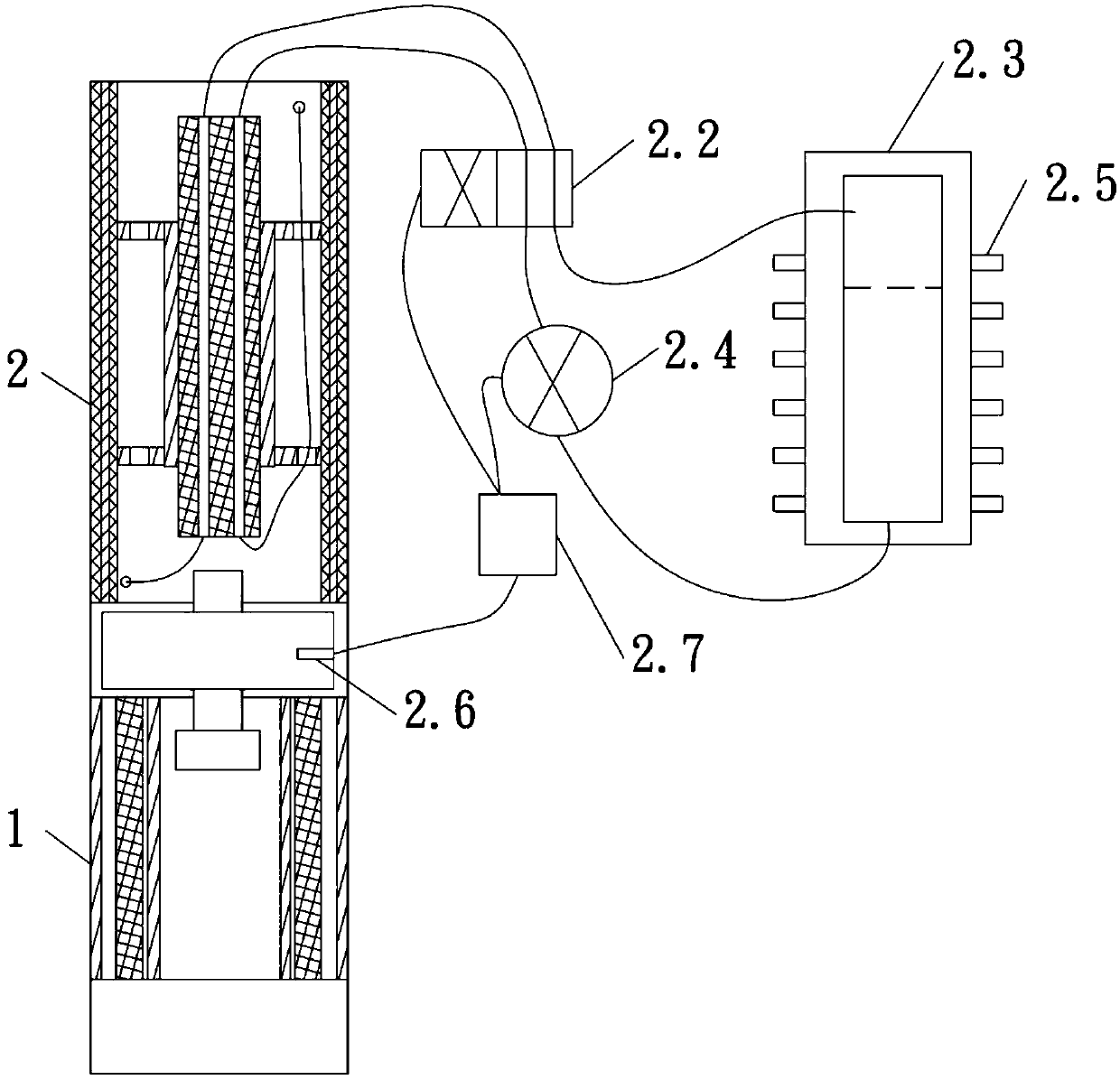
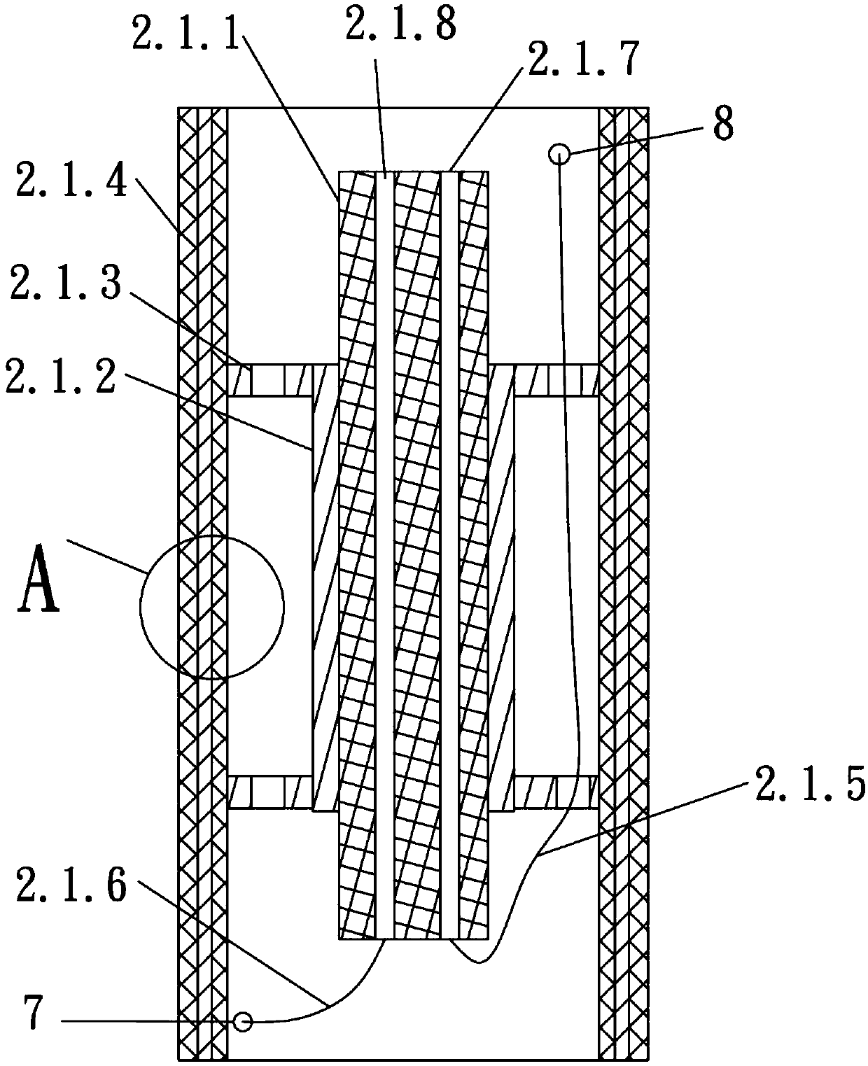
[0033] Such as Figure 1-5 As shown, the heat dissipation system of the electrical equipment includes an air purification device 1 and a temperature adjustment device 2. The temperature adjustment device 2 is installed on the top of the air purification device 1. The air purification device 1 includes an internal support metal filter screen 1.1, an internal Supporting filter base 1.2, spliced ​​annular filter 1.3, spliced ​​annular filter cover 1.4 and top connection seat 1.5, the bottom of the top connection 1.5 is provided with an internal support filter base 1.2, and the internal support filter base 1.2 is connected to the top Seats 1.5 are set in parallel, internal support metal filter screen 1.1 is located between the top connection seat 1.5 and internal support filter screen base 1.2, internal support metal filter screen 1.1 is installed at the center of the upper surface of internal support filter screen base 1.2, internal support metal filter screen The upper end of th...


PUM


Abstract

The invention relates to a heat dissipation system for electrical equipment. The system includes an air purification device and a temperature regulation device; the temperature regulation device is installed on the top of the air purification device; and the air purification device includes an inner support metal filter screen, an inner support filter screen base, a splicing type annular filter screen, a splicing type annular filter screen outer cover, and a top connecting base. Beneficial effects of the system are that: the heat dissipation system for the electrical equipment has the characteristics of simple equipment principle, high reliability, strong applicable environment, environmental protection and energy conservation; and the heat dissipation system is installed in an outdoor field control cabinet, the temperature regulation device is a water-cooled temperature regulation device, a design of a heat dissipation mouth is cancelled, while air temperature conditions in the outdoor field control cabinet are improved, the effect of air purification of the outdoor field control cabinet is also achieved, and so, environment inside the cabinet reaches an ideal environment of various precision instruments and electrical equipment, and the system operates stably, is low in failure rate, and provides a strong guarantee for devices connected to the same.

Description

technical field [0001] The invention relates to a cooling system for electrical equipment, which belongs to the field of electrical equipment. Background technique [0002] The control cabinet is to assemble the switchgear, measuring instrument, protective device and auxiliary equipment in the closed or semiclosed metal cabinet or on the screen width according to the requirements of electrical wiring. and the safety of surrounding equipment. During normal operation, the circuit can be connected or disconnected by means of a manual or automatic switch. Cut off the circuit or alarm with the help of protective electrical appliances in case of failure or abnormal operation. Various parameters in operation can be displayed by means of measuring instruments, and some electrical parameters can also be adjusted to prompt or send out signals for deviations from normal working conditions. Control cabinets are common electrical equipment. [0003] In the actual production process, ...

Claims


Application Information

Patent Timeline
Patent Type & Authority Applications(China)
IPC IPC(8): H05K7/20
CPCH05K7/20136H05K7/20181H05K7/20218
Inventor 贾国英李兴峰徐峰
Owner 山东博能质量检测有限公司
Learn More