Combined SO2/NOx emission reduction method

A combined emission reduction and ammonia desulfurization technology, applied in separation methods, chemical instruments and methods, gas treatment, etc., can solve the problems of high cost and low efficiency of denitrification, achieve high heat exchange effect, realize heat, and realize rational utilization Effect

Inactive Publication Date: 2019-04-02
ANHUI UNIVERSITY OF TECHNOLOGY
View PDF5 Cites 2 Cited by
  • Summary
  • Abstract
  • Description
  • Claims
  • Application Information

AI Technical Summary

Problems solved by technology

[0008] The purpose of the present invention is to provide a method for joint emission reduction of SO2 and NOx for the problem of high denitrification cost or low efficiency of iron ore sintering flue gas in the prior art. The method makes the sintering flue gas after ammonia desulfurization heat up, and realizes the low-cost and high-efficiency denitrification of sintering flue gas

Method used


Image

  • Combined SO2/NOx emission reduction method
  • Combined SO2/NOx emission reduction method
  • Combined SO2/NOx emission reduction method

Examples


Embodiment 1

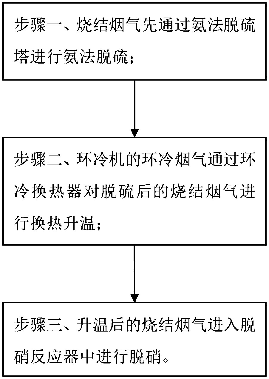
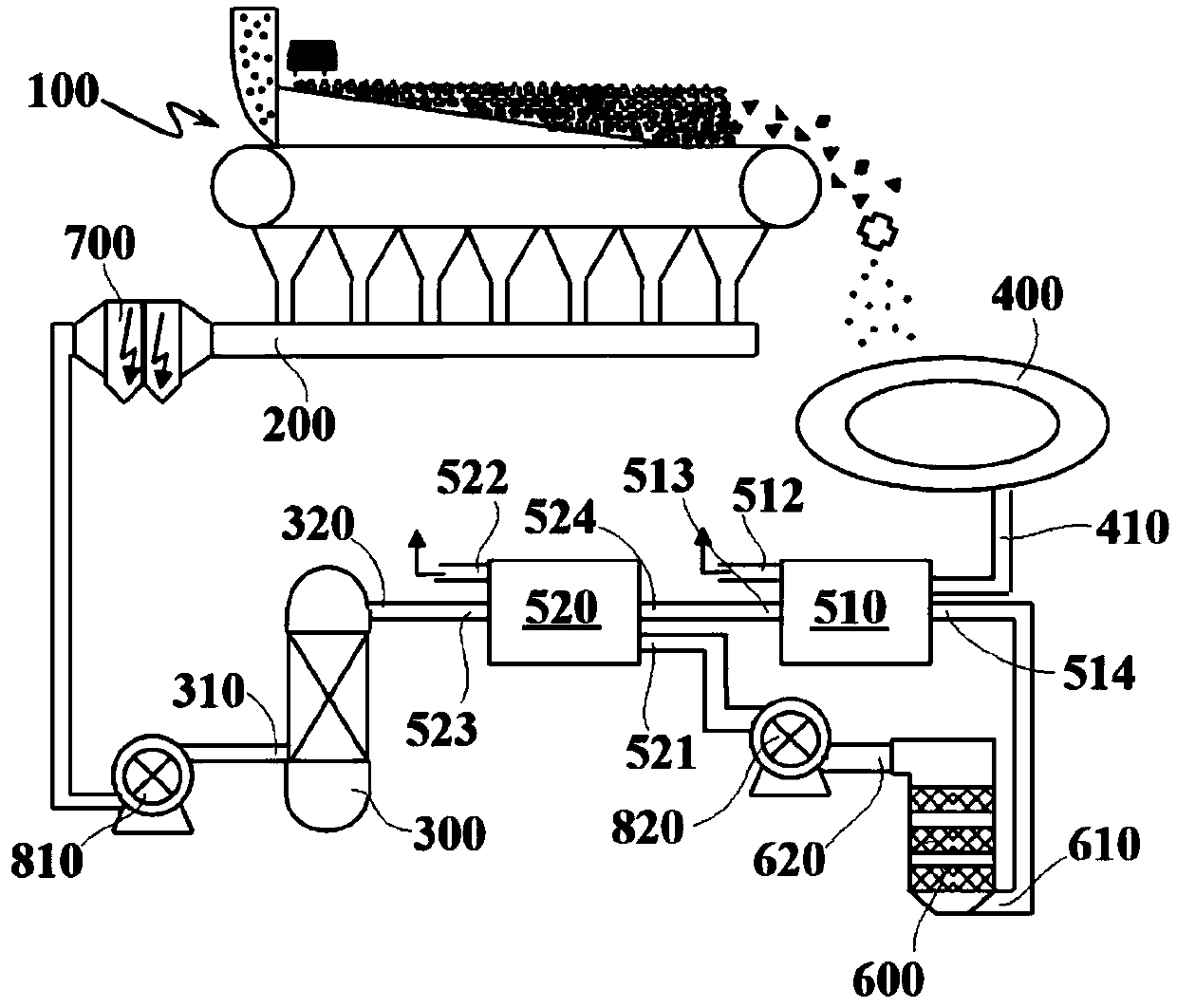
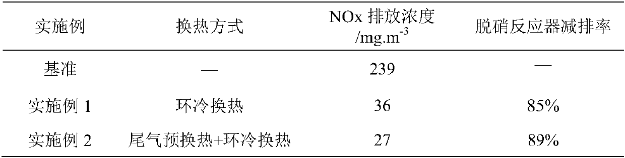
[0039] like figure 1 Shown, a kind of joint emission reduction SO of the present embodiment 2 , NOx method, the sintering flue gas in the main flue 200 first passes through the ammonia desulfurization tower 300 for ammonia desulfurization, and the annular cooling flue gas of the annular cooler 400 passes through the annular cooling heat exchanger 510 to desulfurize the desulfurized sintering flue gas The heat is exchanged to increase the temperature, and the heated sintering flue gas enters the denitration reactor 600 for denitration. In order to realize the above steps and methods, the device used in this embodiment includes a sintering machine 100 , a main flue 200 , an ammonia desulfurization tower 300 , an annular cooler 400 , an annular heat exchanger 510 and a denitrification reactor 600 . During the sintering process, the sintering material is sintered on the sintering machine 100 , and the generated sintering flue gas enters the main flue 200 through drafting. The si...

Embodiment 2

[0055] In this embodiment, on the basis of Embodiment 1, the tail gas after denitrification in the denitrification reactor 600 is passed through the tail gas heat exchanger 520 to perform preheat exchange and temperature rise on the sintering flue gas after desulfurization and before ring cooling heat exchange. In this embodiment, A tail gas heat exchanger 520 is arranged on the pipeline between the ammonia desulfurization tower 300 and the ring cooling heat exchanger 510, and the denitration outlet 620 of the denitration reactor 600 is connected with the tail gas heat exchanger 520 through the pipeline, and the tail gas passes through the tail gas heat exchanger 520 Heat exchange and temperature rise for sintering flue gas.

[0056] The exhaust gas heat exchanger 520 in this embodiment is provided with an exhaust gas heating inlet 521, an exhaust gas heating outlet 522, a first heating inlet 523, and a first heating outlet 524, and the denitrification outlet 620 and the first ...

Embodiment 3

[0065] This embodiment is basically the same as that of Embodiment 1, except that the amount of ammonia sprayed in the ammonia desulfurization tower 300 in this embodiment is 1800m 3 / h, before the sintering flue gas of this embodiment enters the ammonia desulfurization tower 300, the temperature of the flue gas at the desulfurization inlet 310 is 120°C, and the SO 2 The content is 1763mg / Nm 3 , NO x The content is 321mg / Nm 3 ; The sintering flue gas is desulfurized through the ammonia desulfurization tower 300, and the temperature of the sintering flue gas at the desulfurization outlet 320 is 63.5°C, SO 2 The content is 75mg / Nm 3 , NO x The content is 231mg / Nm 3 , the desulfurization rate is 95.7%, and the denitrification rate of ammonia desulfurization tower 300 is 28.0%. And then through the denitrification reactor 600 denitrification, denitrification outlet 620 place NO x Content is 29m 3 / h, the denitrification rate of the denitrification reactor 600 is 87.8%.


PUM


Abstract

The invention provides a combined SO2/NOx emission reduction method and relates to the technical field of sintering pollutant emission reduction. The method includes: performing ammonia desulfurization process on sintering flue gas in a main flue through an ammonia desulfurization column; performing heat exchange on the desulfurized flue gas for increasing temperature by means of circular coolingflue gas in a circular cooling device through a circular cooling heat exchanger; then denitrating the heated sintering flue gas in a denitration reactor. In the method, after the sintering flue gas isdesulfurized and cooled by the ammonia desulfurization column, the desulfurized flue gas is subjected to heat exchange for increasing temperature by means of circular cooling flue gas through a circular cooling heat exchanger, so that after the heat exchange, temperature of the sintering flue gas reaches the required temperature in the denitration reaction in the following denitration reactor. Therefore, by reasonable combination of the ammonia desulfurization process and the denitration reactor, low-cost combined emission reduction of the SO2 and NOx of the sintering flue gas is achieved. The discharged flue gas is also effectively dewhitened.

Description

technical field [0001] The invention relates to the technical field of sintering pollutant emission reduction, more specifically, to a joint emission reduction SO 2 , NOx method. Background technique [0002] With the continuous progress of global ecological construction, the emission reduction of atmospheric pollutants has received more and more attention, among which nitrogen oxides (NO x ) emission reduction situation is particularly severe. According to relevant statistics, NO in the iron and steel industry x Emissions have become one of the three major emission sources of atmospheric nitrogen oxides in China. Among them, the sintering process is the largest NO in the steel plant. x Emission sources account for about 50% to 60% of steel plant emissions. At present, the NO x The emission is difficult to reach the content stipulated in GB28662-2012 "Steel Sintering and Pelletizing Industry Air Pollutant Emission Standard", so the sintering process NO x Research on em...

Claims


Application Information

Patent Timeline
Patent Type & Authority Applications(China)
IPC IPC(8): B01D53/75B01D53/50B01D53/56B01D53/86
CPCB01D53/50B01D53/56B01D53/75B01D53/8628B01D2251/2062B01D2255/20707B01D2255/20723B01D2255/20769B01D2255/20776B01D2258/0283
Inventor 春铁军穆固天龙红明朱梦飞余正伟王平孟庆民魏汝飞狄瞻霞李家新代梦博秦立浩
Owner ANHUI UNIVERSITY OF TECHNOLOGY
Why Eureka
Try Eureka