Optical fiber strain measurement apparatus and optical fiber strain measurement method
A technology of optical fiber strain and measuring device, which is applied in the direction of measuring device, adopting optical device, converting sensor output, etc., can solve the problems that cannot be directly applied to directly modulated semiconductor laser, and achieve the effect of high receiving sensitivity
- Summary
- Abstract
- Description
- Claims
- Application Information
AI Technical Summary
Problems solved by technology
Method used
Image

Examples
no. 1 Embodiment approach
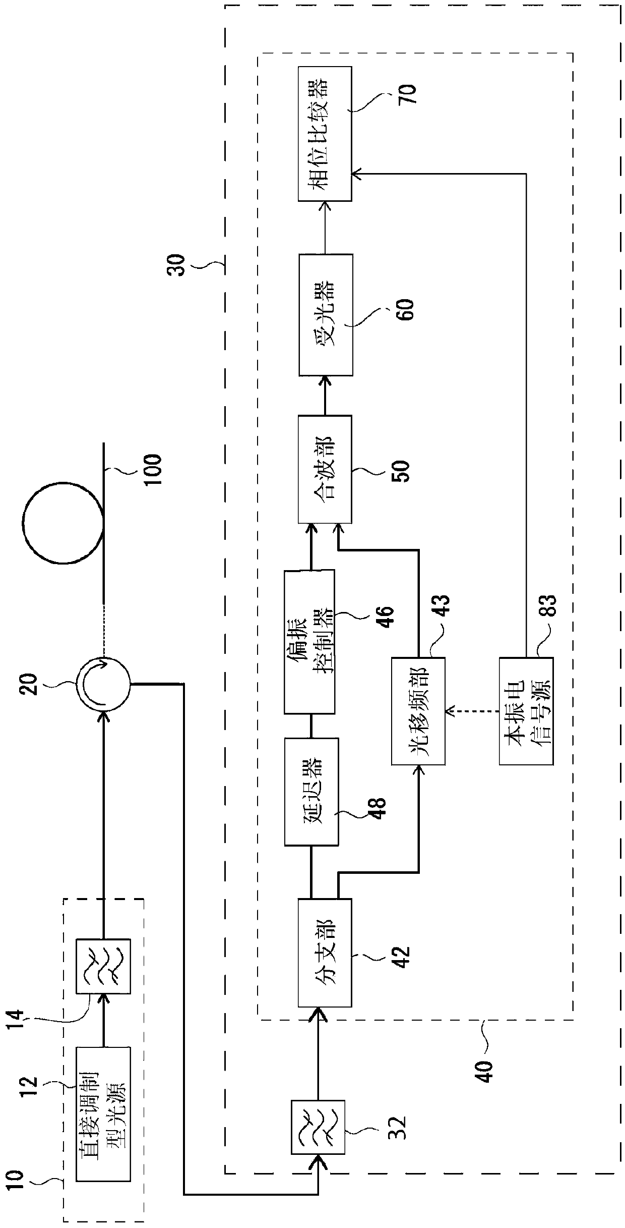
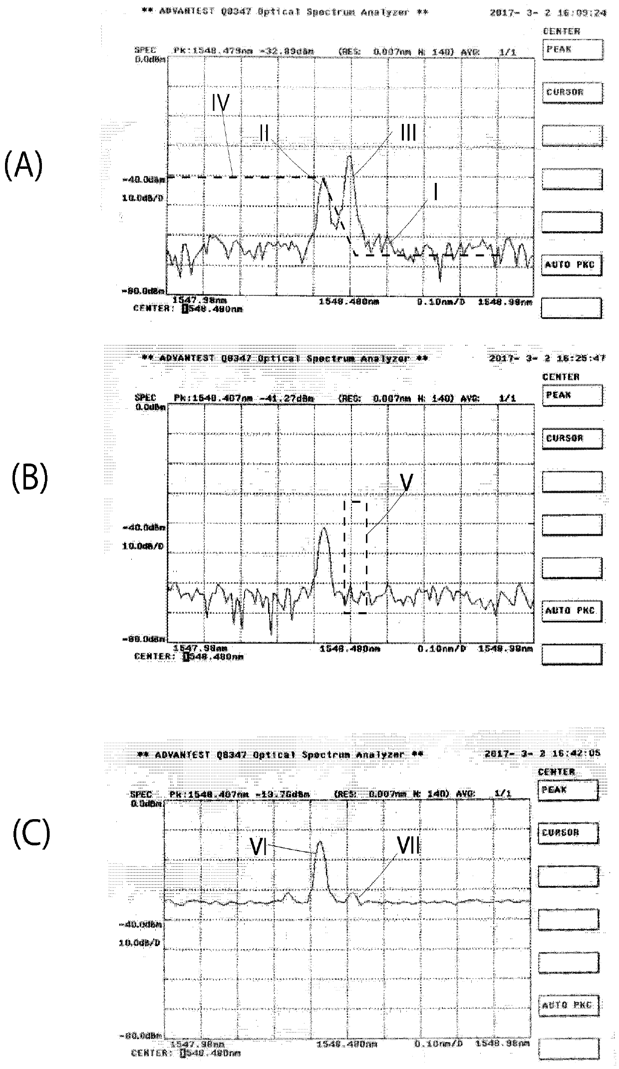
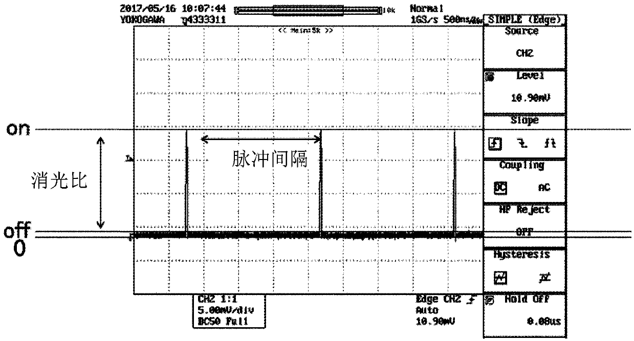
[0039] refer to Figure 1~3 A first embodiment of the optical fiber strain measuring device of the present invention will be described. figure 1 It is a schematic block diagram of the first embodiment of the optical fiber strain measuring device. figure 2 is a graph showing spectral waveforms. exist figure 2 In (A) to (C), the horizontal axis represents the wavelength, and the vertical axis represents the signal intensity. figure 2 (A) represents a spectral waveform output from a direct modulation light source described later, figure 2 (B) shows the spectral waveform output from the optical band-pass filter (BPF) on the transmission side, figure 2 (C) shows the spectral waveform of backscattered light. image 3 It is a diagram showing an optical pulse waveform output from a transmission-side optical band-pass filter (BPF). exist image 3 In , the horizontal axis represents time, and the vertical axis represents signal strength.
[0040] The optical fiber strain m...
no. 2 Embodiment approach
[0067] In BOTDR, when the amount of data increases due to elongation or the like, the spatial resolution may be lowered to reduce the number of samples. In order to lower the spatial resolution, it is necessary to increase the optical pulse width.
[0068] Here, when the optical pulse width is changed, the duty ratio of the signal changes, and the wavelength corresponding to the ON level changes. Figure 4 It is a figure which shows the spectral waveform when the optical pulse width changes.
[0069] exist Figure 4 Among them, the case where the light pulse width is 31.25 ns is shown by curve I, and the case where the light pulse width is 50 ns is shown by curve II.
[0070] When the optical pulse width is increased, the peak of the ON level approaches the peak of the OFF level (noise). That is, since the wavelength of the probe light changes, the wavelength band of Brillouin scattering also changes.
[0071] Therefore, in the optical fiber strain measuring device accordi...
PUM
 Abstract
Description
Claims
Application Information
 - Generate Ideas
- Intellectual Property
- Life Sciences
- Materials
- Tech Scout
- Unparalleled Data Quality
- Higher Quality Content
- 60% Fewer Hallucinations
Browse by: Latest US Patents, China's latest patents, Technical Efficacy Thesaurus, Application Domain, Technology Topic, Popular Technical Reports.
© 2025 PatSnap. All rights reserved.Legal|Privacy policy|Modern Slavery Act Transparency Statement|Sitemap|About US| Contact US: help@patsnap.com