A Control System for Model Oscillation Test in Wind Tunnel Rotating Flow Field

A control system, rotating flow technology, applied in the field of control systems to achieve the effect of improving effectiveness

Active Publication Date: 2021-06-18
中国航空工业集团公司哈尔滨空气动力研究所
View PDF5 Cites 0 Cited by
  • Summary
  • Abstract
  • Description
  • Claims
  • Application Information

AI Technical Summary

Problems solved by technology

[0003] The purpose of the present invention is to provide a control system for model oscillation tests under the rotating flow field in a wind tunnel, which solves the phase relationship between the oscillation axis and the rotation axis when the oscillation axis starts sinusoidal motion in the dynamic test, and the positive zero-crossing movement of the model sinusoidal oscillation The problem of the determination and acquisition of the trigger acquisition point and the synchronization of the aerodynamic data acquisition and the output position signal of the control system

Method used


Image

  • A Control System for Model Oscillation Test in Wind Tunnel Rotating Flow Field

Examples


Embodiment 1

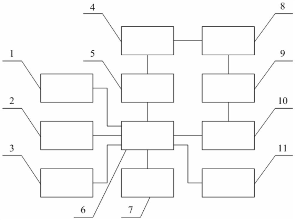
[0009] according to figure 1 As shown, a control system for model oscillation tests under a wind tunnel rotating flow field includes a remote computer, a system master control computer 4 and an acquisition system, and also includes a braking energy absorption module 1, a vibration start point induction module 2, Drive power output module 3, CANopen bus module 5, drive control unit 6, coded signal input module 7, auxiliary unit 8, trigger signal conditioning module 9, trigger signal output module 10 and real-time position output module 11, master control computer through CANopne bus The module 5 communicates with the drive control unit 6, the braking energy absorption module 1, the drive power output module 3, the drive control unit 6, the coded signal input module 7 form a closed-loop control with the rotary shaft motor and the vibration shaft motor, and the drive control unit 6 controls each Shaft motor load parameters, control mode and PID parameters are configured, and the ...


PUM


Abstract

The invention discloses a control system for a model oscillation test under a wind tunnel rotating flow field, which includes a remote computer, a system master control computer and an acquisition system, and also includes a braking energy absorption module, a vibration starting point induction module, and a driving power output module, CANopen bus module, drive control unit, coded signal input module, auxiliary unit, trigger signal conditioning module, trigger signal output module and real-time position output module, the start-of-vibration point sensing module senses the zero position signal of the rotating shaft by optocoupler, and Send the signal to the drive control unit, thereby activating the vibration axis motor to start the vibration axis oscillation, to ensure that the vibration axis can start to vibrate at the zero phase of the rotation axis when the rotation axis motor is at different rotation frequencies; the drive control unit sends a collection trigger signal, and the auxiliary unit The acquisition system is triggered to acquire the balance signal according to the set parameters. The invention realizes the establishment of the rotating flow field and the sinusoidal oscillation motion, and has high system reliability and stability.

Description

technical field [0001] The invention relates to a control system for model oscillation tests under the swirling flow field of a wind tunnel. Background technique [0002] When the aircraft exceeds the stall angle of attack, it is easy to enter a complicated and dangerous spin flight state, which seriously endangers the flight safety of the aircraft. At present, the equipment for researching the aircraft spin mainly simulates the flight situation of the aircraft in the spin state through the belt model test, and analyzes and studies the relevant test data to obtain the necessary information for the aircraft safety design. The control drive system generally uses a traditional inverter motor system to simulate the flight attitude of the aircraft tail spin by changing the rotation frequency and positioning angle, and obtain aerodynamic data through the acquisition system. The sinusoidal oscillating motion is an important content in the study of aircraft spin, and the oscillatin...

Claims


Application Information

Patent Timeline
Patent Type & Authority Patents(China)
IPC IPC(8): G05B23/02G01M9/00G01M9/08
CPCG01M9/00G01M9/08G05B23/0213
Inventor 崔立冬王建锋沈彦杰牟伟强
Owner 中国航空工业集团公司哈尔滨空气动力研究所
Why Eureka
Try Eureka