
Thyristor chip

A thyristor and chip technology, applied in electrical components, electric solid devices, circuits, etc., can solve the problems of slow heat dissipation and small flow area, and achieve the effects of fast heat dissipation, increased flow area, and reduced volume

Inactive Publication Date: 2019-04-02
仪征市坤翎铝业有限公司
View PDF0 Cites 2 Cited by
  • Summary
  • Abstract
  • Description
  • Claims
  • Application Information

AI Technical Summary

Problems solved by technology

[0003] The purpose of the present invention is to provide a thyristor chip to solve the problem of small flow area and slow heat dissipation in the existing thyristor chip unit

Method used


Image

  • Thyristor chip

Examples


Embodiment Construction

[0011] In order to make the object, technical solution and advantages of the present invention clearer, the present invention will be further described below in conjunction with the accompanying drawings and specific embodiments. It should be understood that the specific embodiments described here are only used to explain the present invention, not to limit the present invention. Based on the embodiments of the present invention, all other embodiments obtained by persons of ordinary skill in the art without making creative efforts belong to the protection scope of the present invention.

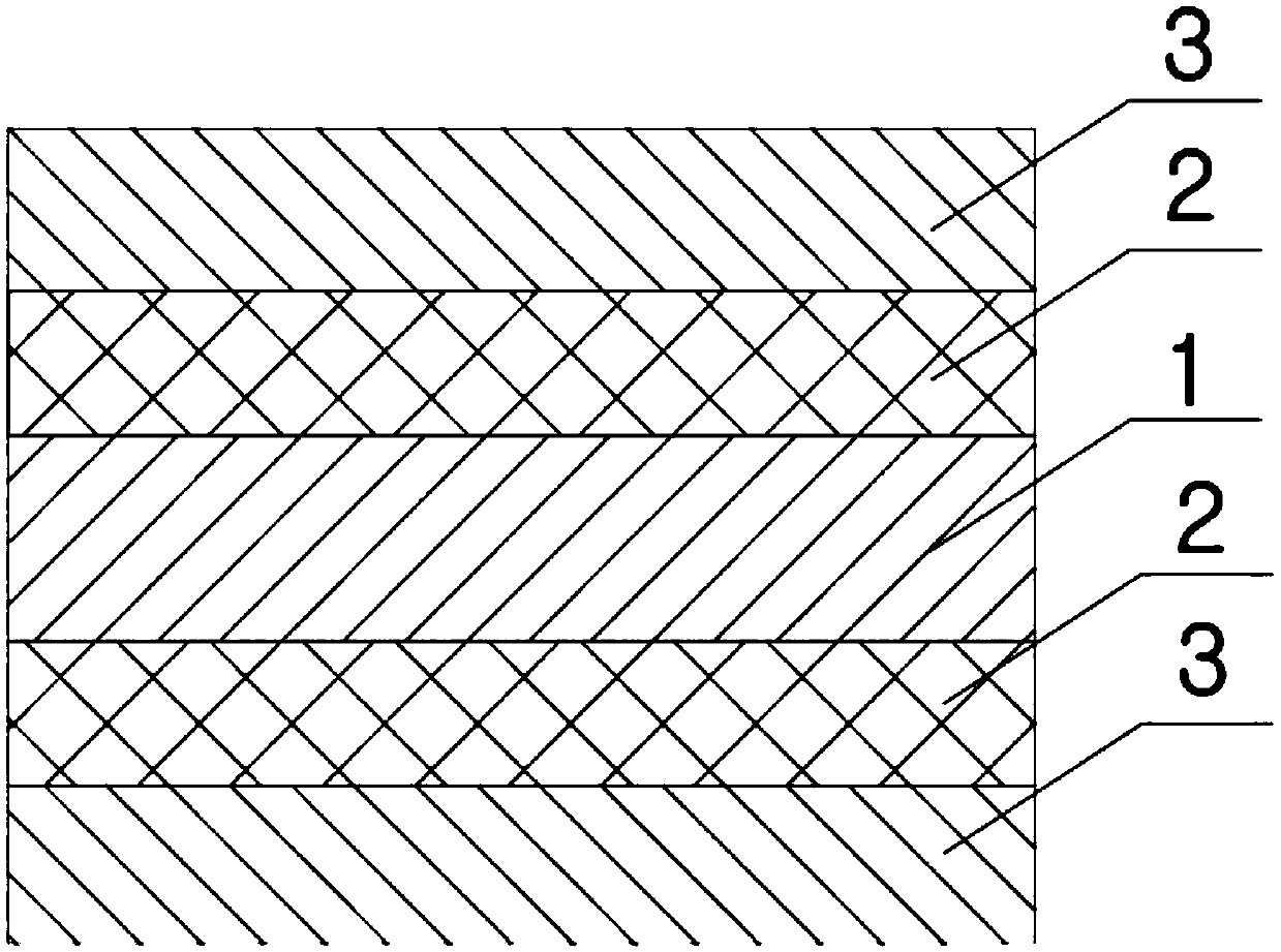
[0012] Examples such as figure 1 As shown, a thyristor chip includes a silicon chip 1, the front and back of the silicon chip 1 are respectively provided with a solder sheet 2; the outer surface of the solder sheet 2 is provided with a copper sheet 3. The diameters of the solder sheet 2 and the copper sheet 3 are 34mm. The thickness of the copper sheet 3 is 0.5-1.5 mm, preferably 1 mm.

[...


PUM


Abstract

The invention relates to a thyristor chip. The thyristor chip comprises a silicon wafer; soldering tin sheets are arranged on a front and a back of the silicon wafer; and a copper sheet is arranged onan outer surface of each soldering tin sheet. The problem that the traditional iron sheet is slow in radiating and low in conductivity is solved; and meanwhile, the problem about hexagonal chip pointdischarge is solved, and the thyristor chip is large in flow area and low in expansion coefficient in comparison with the hexagonal chip under the same volume. The thyristor chip can be extensively applied to the field of the thyristor chip.

Description

technical field [0001] The invention relates to a thyristor chip. Background technique [0002] The thyristor chip is usually composed of a long base region N composed of a silicon chip, a cathode region and an anode region, and an iron sheet arranged on the outermost layer for easy welding, plus a middle solder layer with a total of 7 layers, and usually adopts a hexagonal structure. Due to the corrosion problem of the iron sheet, long-term storage or contact with water during use may easily lead to chip failure. Moreover, the iron sheet has poor current conduction rate, heavy quality, and slow heat dissipation. The hexagonal structure is also small in size, low in conduction rate, and there is a discharge tip, which causes electrostatic interference on the chip. Contents of the invention [0003] The object of the present invention is to provide a thyristor chip, which solves the problems of small flow area and slow heat dissipation in the existing thyristor chip unit....

Claims


Application Information

Patent Timeline
Patent Type & Authority Applications(China)
IPC IPC(8): H01L23/492
CPCH01L23/492H01L23/4924
Inventor 洪越
Owner 仪征市坤翎铝业有限公司
Learn More