
Three-dimensional object manufacturing device and method thereof as well as computer storage medium

A technology for manufacturing equipment and three-dimensional objects. It is applied in the field of additive manufacturing. It can solve the problems that the molding process cannot continue, the cylinder body molding effect is not ideal, and the cutting surface is deformed, so as to achieve the effect of improving powder utilization, low cost, and increasing temperature.

Active Publication Date: 2019-04-05
HUNAN FARSOON HIGH TECH CO LTD
View PDF1 Cites 7 Cited by
  • Summary
  • Abstract
  • Description
  • Claims
  • Application Information

AI Technical Summary

Problems solved by technology

[0004] In the above molding process, although there is an infrared radiation device to heat the entire area to be formed, the heat of the powder on the edge of the cylinder wall will quickly conduct heat conduction through the metal cylinder, resulting in a certain thickness of the powder near the cylinder during the laser sintering process. Always lower than other areas to be formed, however, sintering occurs in this lower temperature area will inevitably cause deformation and warpage of the cut surface after forming, so that the forming process cannot continue
[0005] In order to solve the above problems, the existing technology generally uses a conductive heater to increase the temperature of the four walls of the cylinder to ensure the molding range. However, due to the limitations of the structure, the uniformity of the heater itself, and the heat dissipation of the cylinder, the molding effect near the cylinder is always unsatisfactory.

Method used


Image

  • Three-dimensional object manufacturing device and method thereof as well as computer storage medium
  • Three-dimensional object manufacturing device and method thereof as well as computer storage medium
  • Three-dimensional object manufacturing device and method thereof as well as computer storage medium

Examples


Embodiment Construction

[0028] In order to make the purpose, technical solution and advantages of the present application clearer, the present application will be further described in detail below in conjunction with the accompanying drawings and embodiments. It should be understood that the specific embodiments described here are only used to explain the present application, and are not intended to limit the present application.

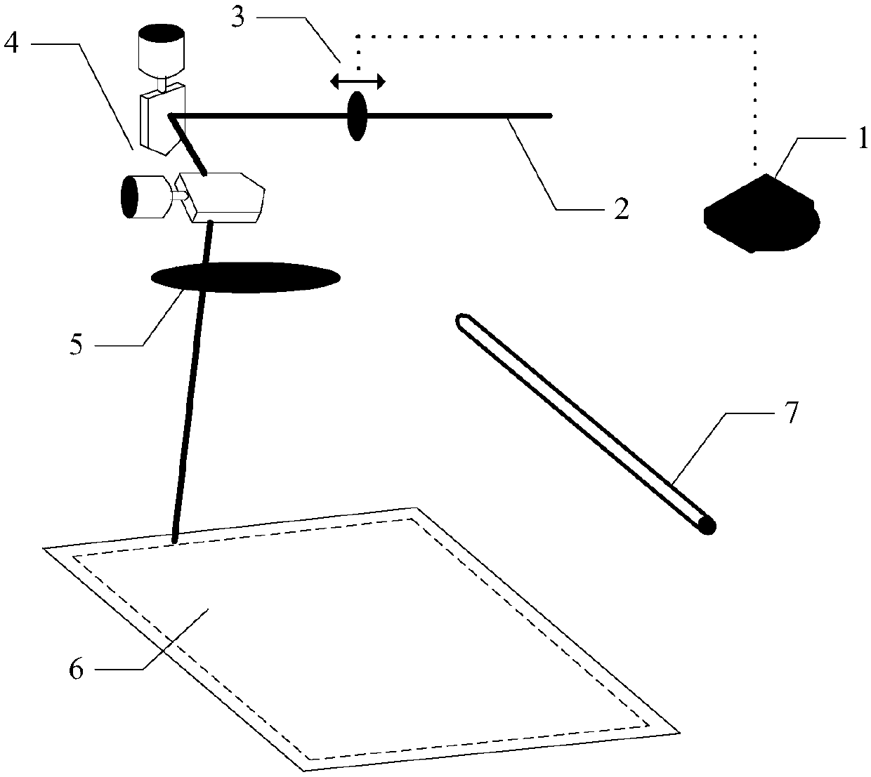
[0029] In the prior art, although those skilled in the art usually preheat the powder layer before laser 2 scanning sintering to increase the temperature of the powder layer and reduce internal stress, those skilled in the art have not found that the edge of the forming cylinder is easy to dissipate heat and cause the cylinder The technical problem of low temperature in the edge area of ​​the wall makes the cut surface after molding deform and warp when the part to be printed is located on the edge of the forming cylinder, which in turn causes the part to continue printing,...


PUM


Abstract

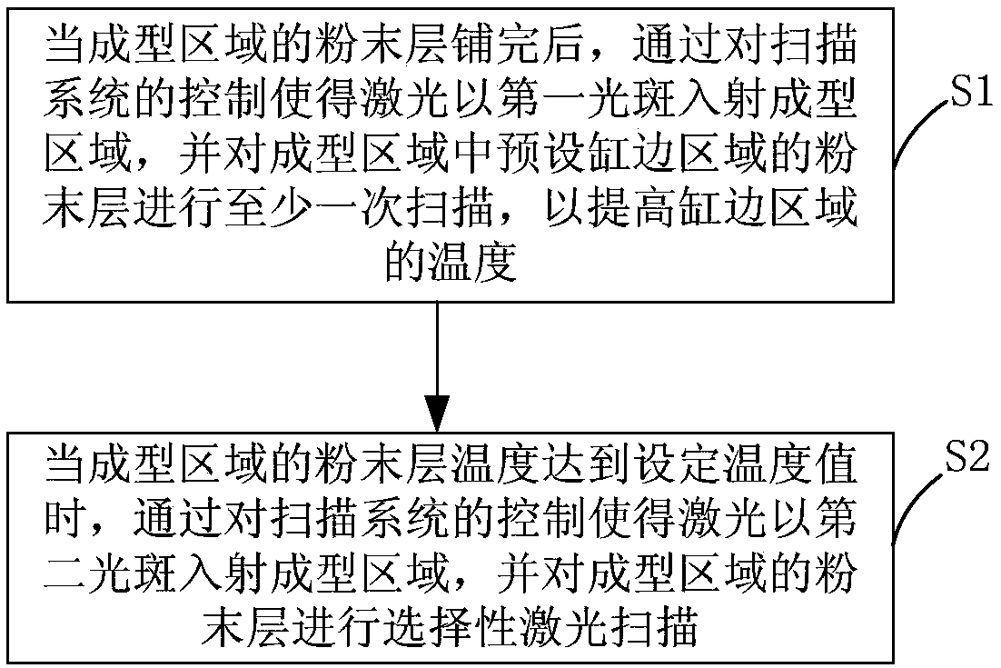
The invention relates to a three-dimensional object manufacturing device and a method thereof as well as a computer storage medium. The device comprises a powder spreading device, an energy source, ascanning system, a heating system and a control system; the powder spreading device is used for spreading powder material on a bottom plate or a selectively-cured layer to form a powder layer; the energy source is used for generating lasers; the heating system is used for preheating the powder layer in a forming area; the control system is used for controlling the scanning system to enlarge lightspots of the lasers before the powder layer in the formed area is subjected to selective scanning and sintering, at least one-time scanning is carried out on the powder layer of a preset cylinder edgearea in the forming area through the lasers with the enlarged light spots under the control of the scanning system, so that the temperature of the cylinder edge area is improved. According to the three-dimensional object manufacturing device and the method thereof as well as the computer storage medium, the temperature of the edge area of a cylinder body is increased, then the area of the formingarea is effectively enlarged, so that the powder utilization rate is improved, and the structure is simple.

Description

technical field [0001] The present application relates to the technical field of additive manufacturing, in particular to a three-dimensional object manufacturing device and method thereof, and a computer storage medium. Background technique [0002] Additive manufacturing technology is an advanced manufacturing technology with distinctive features such as digital manufacturing, high flexibility and adaptability, direct CAD model drive, fast speed, and rich and diverse material types. tooling mold, so the application range is very wide. Selective Laser Sintering (SLS for short) and Selective Laser Melting (SLM for short) are the most rapidly developed additive manufacturing technologies in recent years. [0003] The basic process of selective laser sintering molding is: install an infrared radiation device above the area to be formed to preheat the powder in the area, so that the powder in the area reaches a relatively uniform and stable temperature, and then the scanning s...

Claims


Application Information

Patent Timeline
IPC IPC(8): B29C64/153B29C64/393B29C64/20B29C64/268B33Y30/00B33Y50/02
CPCB33Y30/00B33Y50/02B29C64/153B29C64/20B29C64/268B29C64/393
Inventor 许小曙彭伟鲍光曾艺伶
Owner HUNAN FARSOON HIGH TECH CO LTD
Learn More