Last stage orbit remaining application subsystem attitude control method

A technology for applying subsystems and attitude control, which is applied in the directions of space navigation vehicle guidance devices, space navigation equipment, space navigation aircraft, etc. Design difficulty and other issues, to achieve the effect of being beneficial to ground imaging and data communication, improving attitude control accuracy, and eliminating the influence of time delay

Active Publication Date: 2019-04-05
SHANGHAI ASES SPACEFLIGHT TECH LTD CO
View PDF4 Cites 3 Cited by
  • Summary
  • Abstract
  • Description
  • Claims
  • Application Information

AI Technical Summary

Problems solved by technology

However, for the last stage of the rocket, its attitude is constantly spinning and accompanied by certain nutation in space, and the process of collecting signals by the sensor, the calculation and processing process of the controller, and the actuation process of the actuator will all produce time lags, giving The design of the measurement and control system and the energy system brings difficulties, it is difficult to achieve orientation to the sun, and it is impossible to obtain effective and controllable data

Method used


Image

  • Last stage orbit remaining application subsystem attitude control method
  • Last stage orbit remaining application subsystem attitude control method
  • Last stage orbit remaining application subsystem attitude control method

Examples


Embodiment 1

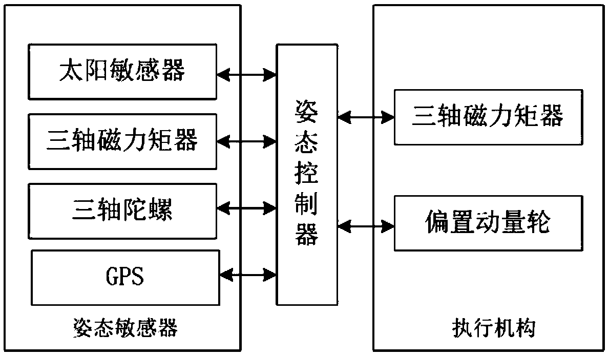
[0084] figure 1 It is a schematic diagram of the system structure of a last-stage track keeping application subsystem in a preferred embodiment of the present invention.

[0085] like figure 1 As shown, this embodiment provides an attitude control system of the last sub-level track keeping application subsystem, which includes: an attitude sensor, an attitude controller, and an actuator.

[0086] The attitude sensor is used to obtain the attitude information of the last sub-level track keeping application subsystem, and output a signal that is a function of the attitude parameters. Attitude sensors include sun sensors, three-axis magnetic torque devices, GPS and three-axis gyroscopes.

[0087] An attitude controller, connected in communication with the attitude sensor, is used to determine the current state of the last-level track-keeping application subsystem according to the attitude information of the last-level track-keeping application subsystem, and the current state i...

Embodiment 2

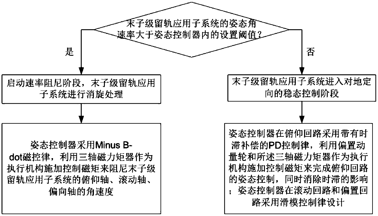
[0091] image 3 It is a flow chart of an attitude control method of the last sub-stage track keeping application subsystem in a preferred embodiment of the present invention.

[0092] like image 3 As shown, a method for attitude control of the last sub-level orbit application subsystem, including:

[0093] After the last sub-level orbit-keeping application subsystem enters the task setting orbit, the attitude controller pre-stores the setting threshold of the attitude angular rate of the last sub-level orbit-keeping application subsystem. When the attitude angular rate is greater than the attitude controller Set the threshold within the threshold, start the rate damping stage, and perform derotation processing on the last sub-level orbit-keeping application subsystem; when the attitude angular rate is less than or equal to the setting threshold in the attitude controller, the last sub-level orbit-staying application The subsystem enters the ground-oriented steady-state cont...

Embodiment 3

[0170] Simulation example:

[0171] The on-orbit flight stage of the last sub-level application subsystem for orbital retention is simulated, and the simulation input conditions are:

[0172] a) Running track

[0173] Orbit Type: Sun Synchronous Orbit

[0174] Orbit height: 539km

[0175] Orbit inclination: 97.5553deg

[0176] Orbit eccentricity: 0

[0177] b) Satellite mass characteristics

[0178] Satellite mass: 8.3±0.5kg

[0179] Satellite size: 110mm×231.7mm×346mm

[0180] Satellite inertia: I xx =0.088kg·m 2 , I yy =0.116kg·m 2 , I xx =0.044kg·m 2

[0181] 1) B-dot damping simulation

[0182] Taking the rate damping stage as an example, the simulation is carried out. The specific parameters and simulation results are as follows:

[0183] a) Initial pose

[0184] Attitude angle: [10; 10; 10] deg

[0185] Angular speed of rotation: [-3; -3; -3] deg / sec

[0186] b) Control parameters

[0187] Control cycle: 1sec

[0188] Damping Gain: 3e5

[0189] The s...


PUM


Abstract

The invention discloses a last stage orbit remaining application subsystem attitude control method. The method includes the steps that when a last stage orbit remaining application subsystem is in a rate damping period, an attitude controller adopts a Minus B-dot magnetic control law, a three-axis magnetic torquer is used as an execution mechanism for applying control magnetic torque, so that theangular speeds of a pitching axis, a rolling axis and a deviation axis of the last stage orbit remaining application subsystem are damped, and the last stage orbit remaining application subsystem is racemized; and when the last stage orbit remaining application subsystem is in a steady state control period, the attitude controller adopts a PD control law with time-lag compensation on a pitching loop, a bias momentum wheel and the three-axis magnetic torquer are used as execution mechanisms for applying the control magnetic torque, so that attitude control of the pitching loop is finished, anda rolling / yawing loop adopts sliding mode controller design. The sun pointing problem of the last stage orbit remaining application subsystem is solved, meanwhile, time-lag influence is eliminated, and the attitude control accuracy of the last stage orbit remaining application subsystem is improved.

Description

technical field [0001] The invention belongs to the technical field of spacecraft control, and relates to an attitude control method, in particular to an attitude control method of the last sub-stage orbital application subsystem. Background technique [0002] In the past, after every rocket launch in various countries, as the first stage rocket, the second stage rocket and the fairing fall off and return to the ground, the last stage of the rocket will enter orbit along with its payload and occupy precious orbital resources in space for a long time. It poses a safety threat to spacecraft in orbit and is currently the largest space junk. Using the measurement system carried by the last sub-stage of the launch vehicle to stay in orbit, the original last sub-stage of the rocket can be transformed into a low-cost scientific experiment and communication platform, which can turn waste into treasure. [0003] The attitude of the traditional aerospace vehicle is controllable, and ...

Claims


Application Information

Patent Timeline
IPC IPC(8): B64G1/28B64G1/36
CPCB64G1/285B64G1/363B64G1/366B64G1/245B64G1/369
Inventor 曾占魁郑琦邹旭蒋丽丽青志能吴俊杰魏然江炜万玉柱
Owner SHANGHAI ASES SPACEFLIGHT TECH LTD CO
Why Eureka
Try Eureka