Examination heating device for crank case breather pipe, breather pipe, ventilating system and automobile

A heating device and crankcase technology, which is applied in crankcase ventilation, fuel heat treatment device, charging system, etc., can solve the problems of reduced service life of the pipeline, long reaction time of the supercharger, high pressure of the intercooling system, etc. Achieve the effect of saving installation space, avoiding rapid aging, and saving space

Active Publication Date: 2019-04-05
DONGFENG MOTOR CORP HUBEI
View PDF7 Cites 5 Cited by
  • Summary
  • Abstract
  • Description
  • Claims
  • Application Information

AI Technical Summary

Problems solved by technology

Using this scheme has the following disadvantages: 1. When the system fails, the OBD diagnosis system is in a power-off state, so it is impossible to realize the OBD diagnosis when the crankcase ventilation system cannot be exempted; 2. When the hot zone is working, due to The ambient temperature is high, and the continuous heating of the electric heating unit will increase the ambient temperature and reduce the service life of the pipeline
[0004] Furthermore, the layout direction of the existing crankcase ventilation pipe mainly refers to the non-fixed direction of the boundary layout, which will cause the mixed gas to condense and flow back, causing the liquid to accumulate and emulsify at the PCV valve, and the PCV will be blocked when the car is parked for a long time Valve, the PCV valve cannot be opened normally after starting up, resulting in the increase of crankcase pressure and the technical problem of oil increase
[0005] Further, the existing layout of various pipelines installed on the supercharged engine has the following disadvantages. When the vehicle decelerates rapidly, the throttle opening becomes smaller, but the supercharger takes a long time to respond and it is still running at high speed. Therefore, the pressure of the intercooling system will be too high, and the gas will leak into the atmosphere. In severe cases, the pipeline will explode.

Method used


Image

  • Examination heating device for crank case breather pipe, breather pipe, ventilating system and automobile
  • Examination heating device for crank case breather pipe, breather pipe, ventilating system and automobile
  • Examination heating device for crank case breather pipe, breather pipe, ventilating system and automobile

Examples


Embodiment Construction

[0030] The present invention will be further described below in conjunction with the accompanying drawings.

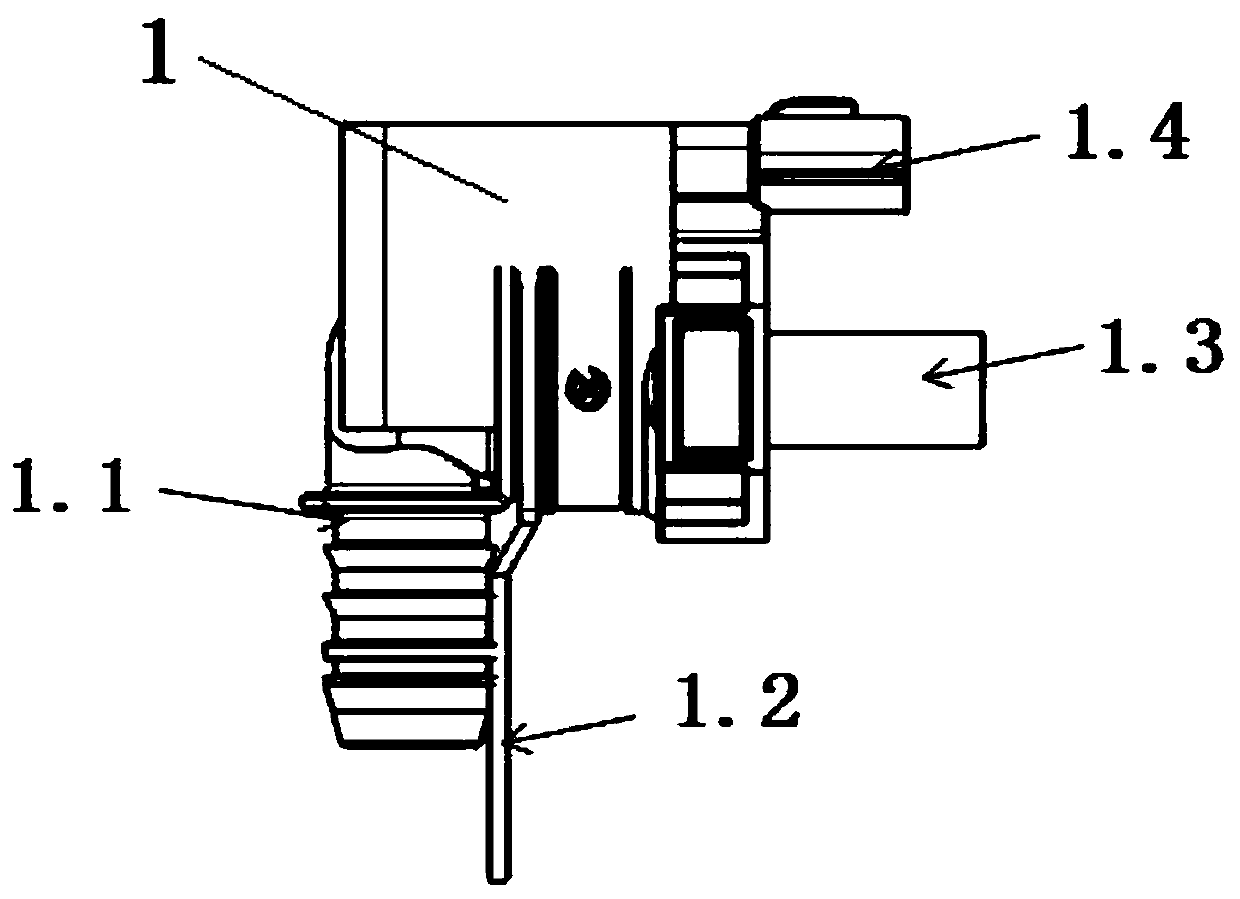
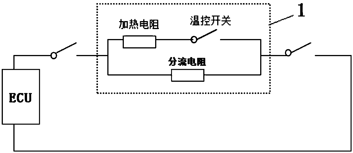
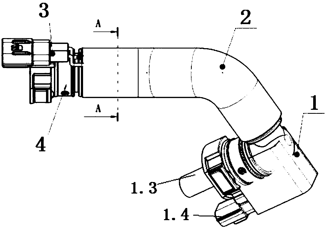
[0031]As shown in the accompanying drawings of the description, the technical solution provided by the present invention is a diagnostic heating device for crankcase ventilation pipes, which includes an outer shell 1, and the outer shell 1 is provided with an air outlet pipe 1.1 for communicating with the crankcase. It is used to connect the guide joint 1.2 of the PVC valve, the intake pipe 1.3 for connecting the engine intake main pipe and the ECU joint 1.4 for connecting the vehicle ECU, the guide joint 1.2 is electrically connected with the ECU joint 1.4, and the air outlet pipe 1.1 is communicated with the air intake pipe 1.3, The intake pipe 1.3 is made of heat-conducting material, and the outer casing 1 is provided with a parallel diagnostic circuit and a heating circuit. After the diagnostic circuit and the heating circuit are connected in parallel, they are inte...


PUM


Abstract

The invention discloses an examination heating device for a crank case breather pipe, a breather pipe, a ventilating system and an automobile. The device comprises a housing, wherein an air outlet pipe which communicates with a crank case, a conductor which is connected to a PVC valve, an air inlet pipe which communicates with a main air inlet pipe of an engine, and an ECU joint which is connectedto an automobile ECU are arranged on the housing; the conductor is electrically connected to the ECU joint; the air outlet pipe communicates with the air inlet pipe which is manufactured through a heat transferring material; an examination circuit and a heating circuit which are connected in parallel are arranged in the housing and are both electrically connected to the automobile ECU through theECU joint; and the heating circuit is connected to the air inlet pipe. The device is simple in structure, and convenient to use; the crank case breather pipe is prevented from being iced during working in a cold area; parts of an existing heating device are prevented from quick aging under high temperature in summer; and meanwhile, the whole-process OBD examination can be performed while the automobile is in running.

Description

technical field [0001] The invention belongs to the technical field of engine intake systems, and in particular relates to a diagnostic heating device for a crankcase ventilation pipe, a diagnostic heating type crankcase ventilation pipe and a forced ventilation system for an automobile engine crankcase. Background technique [0002] At present, automobile engines adopt a forced crankcase ventilation system, which guides the blow-by gas generated during engine operation into the intake manifold for re-combustion. When the engine is working, a part of blow-by gas will be generated, which includes unburned mixture gas, water vapor and exhaust gas. The greater the engine load, the more blow-by gas will be formed. The blow-by gas entering the oil pan will dilute the engine oil, accelerate the oxidation and deterioration of the oil, and cause the performance of the oil to decline; the acid gas in the blow-by gas enters the lubrication system, which easily leads to corrosion of pa...

Claims


Application Information

Patent Timeline
Patent Type & Authority Applications(China)
IPC IPC(8): F01M13/00F02B77/08F02M35/10F02M31/13
CPCF01M13/00F01M13/0033F02B77/083F02M31/13F02M35/10314
Inventor 魏爽许文志汪国民刘元林可为孙坤常菁菁
Owner DONGFENG MOTOR CORP HUBEI
Why Eureka
Try Eureka