Energy-saving and environmental-friendly layer-burning boiler suitable for solid fuel and processing method of layer-burning boiler

A treatment method and boiler technology, applied in the direction of solid fuel combustion, combustion method, combustion air/fuel supply, etc., can solve the problems of low fuel burnout rate, small boiler load, and reduce coal burnout rate, etc., to achieve Effect of improving fuel burnout rate and reducing heat loss

Inactive Publication Date: 2019-04-05
YANKUANG GRP CO LTD +1
View PDF8 Cites 3 Cited by
  • Summary
  • Abstract
  • Description
  • Claims
  • Application Information

AI Technical Summary

Problems solved by technology

Although the chain grate can control NO x However, because the pre-combustion chamber is set in the stove, the coal is partially pre-combusted, which will cause high combustion intensity, which is not conducive to combustion control and optimization of the thermal environment; at the same time, in the front air chamber The introduction of steam is not conducive to the control and adjustment of gasification, thereby reducing the burnout rate of coal combustion
[0005...

Method used


Image

  • Energy-saving and environmental-friendly layer-burning boiler suitable for solid fuel and processing method of layer-burning boiler
  • Energy-saving and environmental-friendly layer-burning boiler suitable for solid fuel and processing method of layer-burning boiler
  • Energy-saving and environmental-friendly layer-burning boiler suitable for solid fuel and processing method of layer-burning boiler

Examples


Embodiment 1

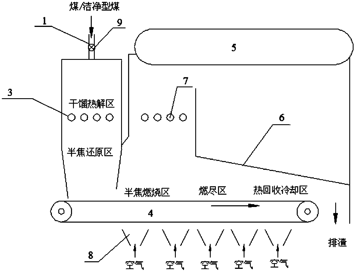
[0070] This embodiment provides a layer fired boiler, such as figure 1 As shown, the furnace body of the layer-fired boiler includes a first cavity and a second cavity connected at the bottom; the top of the first cavity is provided with a coal filling port 1, and the middle part of the first cavity is provided with a pre-combustion air pipe 3, The area above the pre-combustion air pipe 3 in the first chamber is the dry distillation pyrolysis area, and the area below the pre-combustion air pipe 3 is the semi-coke reduction pre-combustion area; the first chamber and the lower part of the second chamber are provided with a first Chain grate 4, the furnace wall side of the first cavity is connected to the first chain grate 4, and there is a space for material circulation between the first cavity and the second cavity and the first chain grate 4;

[0071] The top of the second cavity is provided with a steam drum 5, and the bottom of the steam drum 5 is provided with a back arch 6...

Embodiment 2

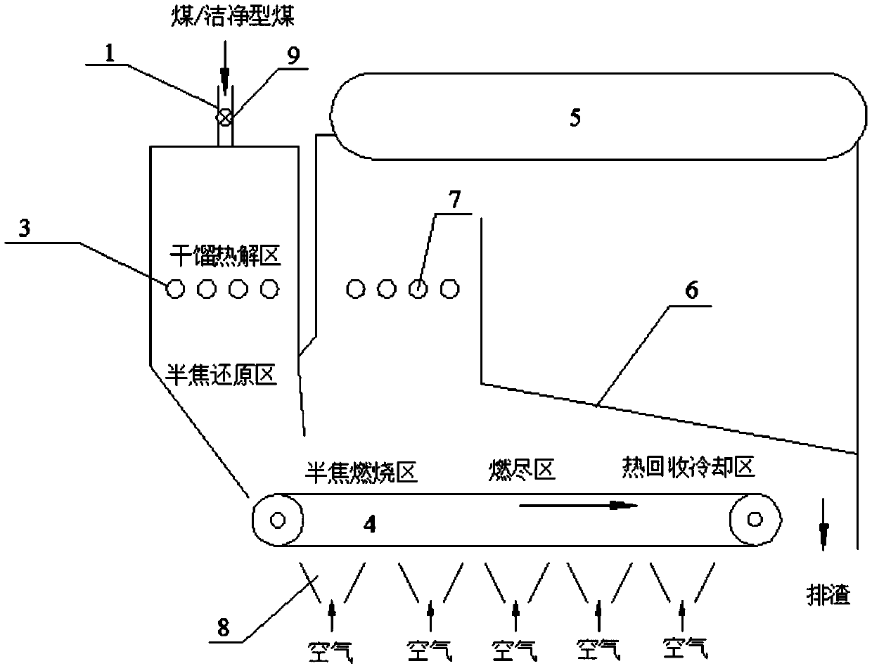
[0080] This embodiment provides a layer fired boiler, such as figure 2As shown, the furnace body of the layer-fired boiler includes a first cavity and a second cavity connected at the bottom; the top of the first cavity is provided with a coal filling port 1, and the middle part of the first cavity is provided with a pre-combustion air pipe 3, The area above the pre-combustion air pipe 3 in the first chamber is the dry distillation pyrolysis area, and the area below the pre-combustion air pipe 3 is the semi-coke reduction pre-combustion area; the first chamber and the lower part of the second chamber are provided with a first Chain grate 4, the furnace wall side away from the side of the steam drum in the first cavity is inclined, and is connected with the first chain grate 4 to shorten the length of the first chain grate 4, the first cavity is close to the steam drum There is a gap for material circulation between one side and the first chain grate 4;

[0081] The top of th...

Embodiment 3

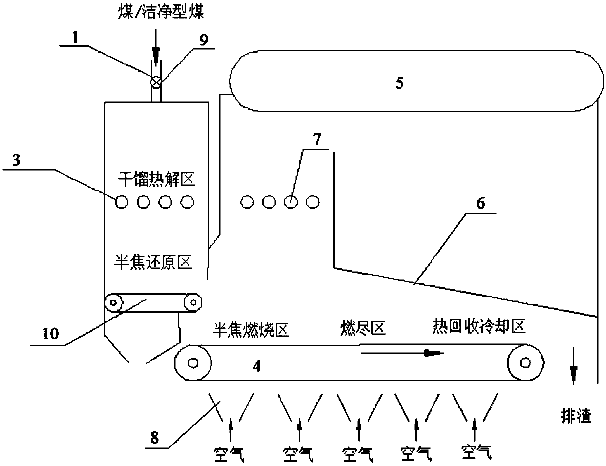
[0090] This embodiment provides a layer fired boiler, such as image 3 As shown, the furnace body of the layer-fired boiler includes a first cavity and a second cavity connected at the bottom; the top of the first cavity is provided with a coal filling port 1, and the middle part of the first cavity is provided with a pre-combustion air pipe 3, The area above the pre-combustion air pipe 3 in the first chamber is the dry distillation pyrolysis area, and the area below the pre-combustion air pipe 3 is the semi-coke reduction pre-combustion area; the first chamber and the lower part of the second chamber are provided with a first Chain grate 4, below the semi-coke reduction pre-combustion zone in the first cavity, a second chain grate 10 is arranged above the first chain grate 4, and the running length of the second chain grate 10 is not longer than that of the first cavity The width of body, there is a gap for material circulation between the side of the first cavity close to th...


PUM


Abstract

The invention provides an energy-saving and environmental-friendly layer-burning boiler suitable for solid fuel and a processing method of the layer-burning boiler. A boiler body of the layer-burningboiler is internally provided with a first cavity and a second cavity with the bottoms communicating with each other, a pre-burning air opening is formed in the middle boiler wall of the first cavityand/or a pre-burning air pipe is arranged in the middle of the first cavity, the areas/the area, on the upper part of the pre-burning air opening and/or on the upper part of the pre-burning air pipe,inside the first cavity are/is destructive distillation pyrolysis areas/ a destructive distillation pyrolysis area, the areas/the area, on the lower part of the pre-burning air opening and/or on the lower part of the pre-burning air pipe, inside the first cavity are/is semi-coke reduction pre-burning areas/ a semi-coke reduction pre-burning area, a first chain grate is arranged on the lower partsof the first cavity and the second cavity, a steam drum is arranged at the top of the second cavity, a rear arch is arranged below the steam drum, and at least two air chambers are arranged below thefirst chain grate. According to the energy-saving and environmental-friendly layer-burning boiler suitable for the solid fuel and the processing method of the layer-burning boiler, nitrogen oxides generated by burning are converted into harmless nitrogen through a reaction with reducing pyrolysis gas and semi-coke in a low-nitrogen pre-burning mode, and through methods such as combining pyrolysisdesulfurization and burning desulfurization and pyrolysis products of coal to form reburning denitration, emission of multi-pollutants such as SOx, NOx, and CO is effectively reduced.

Description

technical field [0001] The invention belongs to the field of coal combustion equipment, and relates to a layer-fired boiler and a processing method thereof, in particular to an energy-saving and environment-friendly layer-fired boiler suitable for solid fuel and a processing method thereof. Background technique [0002] Coal-fired bed-fired boilers are one of the main coal utilization methods in my country and are widely used in heating and industrial production processes. The traditional chain grate furnace in my country adopts single-side ignition during operation. During operation, the coal burns on the grate as it moves along with the grate, and the combustion of the fuel layer along the length of the grate has obvious partitions. [0003] CN 103697459A discloses a horizontal coal-fired full-automatic hot water boiler to solve the problems of low thermal efficiency of existing coal-fired boilers and insufficient coal in the combustion process, resulting in environmental ...

Claims


Application Information

Patent Timeline
IPC IPC(8): F23B10/00F22B31/00F23L1/02F23L9/02
CPCF23B10/00F22B31/00F23B30/08F23B90/04F23B90/06F23L1/02F23L9/02
Inventor 王振平郑元刚杨晓辉邢涛李亚宋令坡王海苗
Owner YANKUANG GRP CO LTD
Why Eureka
Try Eureka