Ultrasonic vibration lens micro-rotation assisted laser machining device

A technology of ultrasonic vibration and auxiliary laser, which is applied in the direction of laser welding equipment, metal processing equipment, manufacturing tools, etc., can solve the problems of no laser focus measurement method, can not guarantee the processing quality, affect the surface quality of the workpiece, etc., achieve simple structure, improve The effect of machining surface quality and small heat-affected zone

Inactive Publication Date: 2019-04-12
NORTHEASTERN UNIV
View PDF6 Cites 13 Cited by
  • Summary
  • Abstract
  • Description
  • Claims
  • Application Information

AI Technical Summary

Problems solved by technology

The focus position measurement methods for laser focusing mainly include inductive displacement sensor detection method, capacitive sensor detection method, printing method, inclined plate method, blue spark method, etc. The geometric error of the machine tool, the deformation of the machine tool under the load force, and the thermal deformation of the workpiece during the processing will cause the deviation of the laser focus position. Therefore, there is currently no accurate laser focus measurement method, resulting in the inability to guarantee high-precision processing quality; The core element in processing is the focus of the laser focus. The existing technical means cannot accurately measure the position of the laser focus, but can only estimate the focus position. The energy of the focus of the laser focus is the highest, so laser processing generally uses this position. processing, but this position is difficult to determine, and at the same time, due to the thermal stress in laser processing, cracks are generated on the processed surface, which affects the surface quality of the workpiece

Method used


Image

  • Ultrasonic vibration lens micro-rotation assisted laser machining device
  • Ultrasonic vibration lens micro-rotation assisted laser machining device
  • Ultrasonic vibration lens micro-rotation assisted laser machining device

Examples


Embodiment Construction

[0028] The present invention will be further described in detail below in conjunction with the accompanying drawings and embodiments.

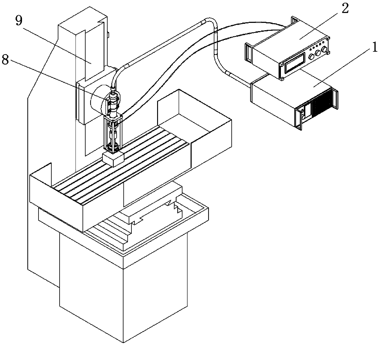
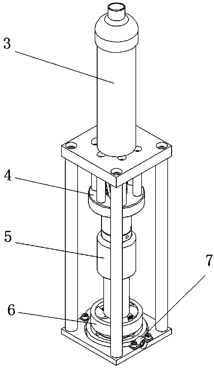
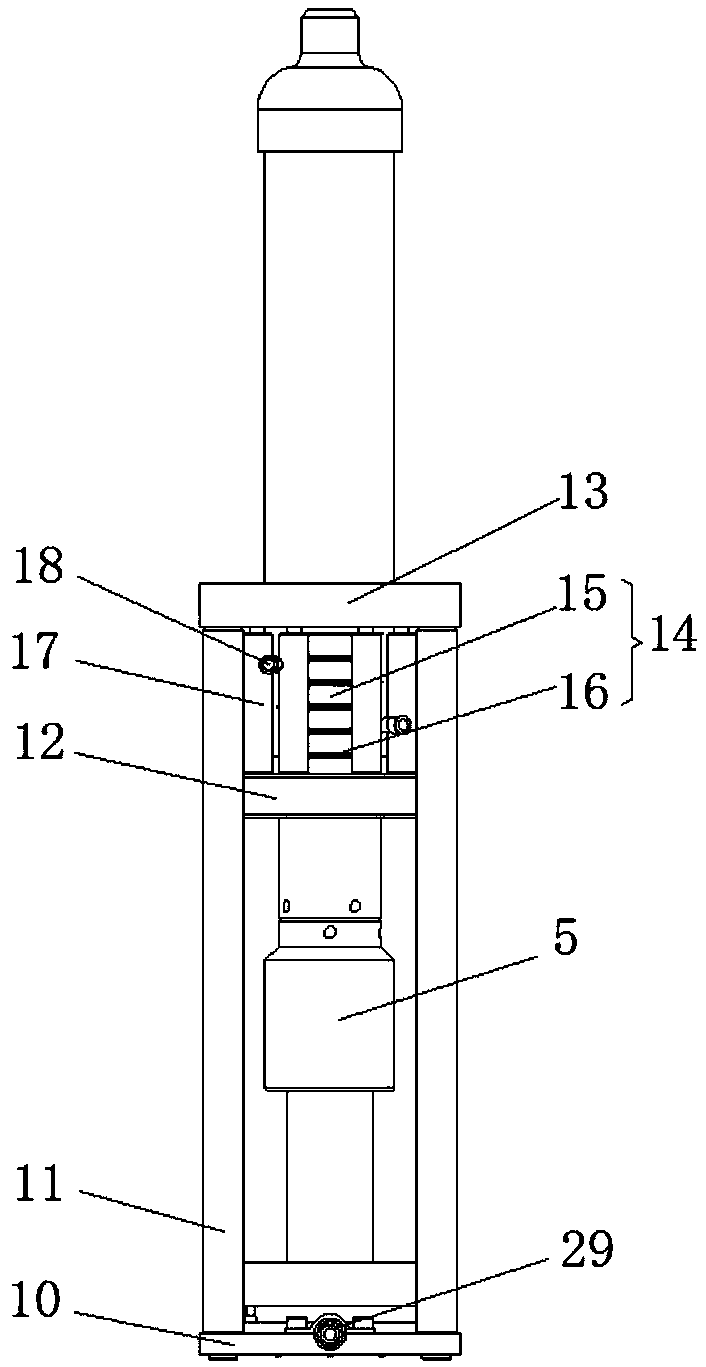
[0029] like figure 1 , figure 2 and Figure 8 As shown, an ultrasonic vibrating lens micro-rotation auxiliary laser processing device includes a laser generator 1 and an ultrasonic generator 2, and the output end of the laser generator 1 is connected to one end of the collimating mirror 3 of the laser working head through an optical fiber terminal. The laser working head includes a collimating mirror 3, an ultrasonic transducer 4, a horn 5, a focusing lens micro-rotation mechanism 6 and a fixing frame, and the laser working head is fixed by a collimating mirror 3, clips 8 and hexagon socket bolts On the machine tool spindle 9, the fixed frame includes a fixed frame bottom plate 10, and the middle part of the upper surface of the fixed frame bottom plate 10 is provided with a focusing lens micro-rotation mechanism 6, and the top of the focus...


PUM


Abstract

The invention discloses an ultrasonic vibration lens micro-rotation assisted laser machining device. The ultrasonic vibration lens micro-rotation assisted laser machining device comprises a laser generator and an ultrasonic generator, the output end of the laser generator is connected with one end of a collimating lens of a laser working head through an optical fiber terminal, the laser working head comprises the collimating lens, an ultrasonic transducer, an amplitude-change rod, a focusing lens micro-rotation mechanism and a fixing frame, the laser working head is fixed to a machine tool spindle through the collimating lens, a clamp and internal hexagonal bolts, the fixing frame comprises a fixing frame bottom plate, the focusing lens micro-rotation mechanism is arranged in the middle ofthe upper surface of the fixing frame bottom plate, the top of the focusing lens micro-rotation mechanism and one end of the amplitude-change rod are in threaded connection, the other end of the amplitude-change rod and a lower cover plate of the ultrasonic transducer are in threaded connection, and the fixing frame bottom plate and an upper cover plate of the ultrasonic transducer are fixedly mounted through four connecting columns. By controlling the ultrasonic vibration amplitude and a rotating shaft sleeve, the size of a trapezoidal column focus formed by a laser focusing lens is finely adjusted, and the laser machining device can finely adjust the shape dimension of the focus.

Description

technical field [0001] The invention belongs to the technical field of ultrasonic vibration composite laser processing, and in particular relates to an ultrasonic vibration lens micro-rotation-assisted laser processing device. Background technique [0002] With the rapid development of the manufacturing industry, the requirements for machining accuracy and machining efficiency of mechanical parts are getting higher and higher. In mechanical processing, the most basic and commonly used precision processing method is cutting processing, which plays an important role in the processing and production of various industries such as machinery, electronics, construction, etc. There are many factors that determine the accuracy and efficiency of cutting processing, such as Machine tools, cutting tools, workpieces, etc., among which cutting tools have the most obvious influence on them. The mechanical properties and processing performance of the tool material directly affect the servi...

Claims


Application Information

Patent Timeline
Patent Type & Authority Applications(China)
IPC IPC(8): B23K26/00B23K26/04B23K26/06B23K26/073B23K26/70
CPCB23K26/00B23K26/04B23K26/06B23K26/073B23K26/70B23K26/702
Inventor 邹平康迪吴昊王文杰田英健徐辑林
Owner NORTHEASTERN UNIV
Why Eureka
Try Eureka