Drying device for fabric printing and dyeing

A drying device, a technology for textile printing and dyeing, applied in the processing of textile materials, textile and papermaking, transportation and packaging, etc., can solve the problems of unstable fixation of textile printing and dyeing items, uneven drying, and slow drying speed.

Inactive Publication Date: 2019-04-12
泉州智驰自动化机械有限公司
View PDF2 Cites 2 Cited by
  • Summary
  • Abstract
  • Description
  • Claims
  • Application Information

AI Technical Summary

Problems solved by technology

[0012] The invention provides a drying device for textile printing and dyeing through improvement. By setting up a rotating mechanism, after the motor works, the output shaft at the front end drives the driving wheel to rotate, and the transmission is carried out through the transmission belt, and at the same time drives the first driven wheel and the second driven wheel. The moving wheel rotates to rotate the shaft seat welded at the left end, and the right end of the clamping mechanism is plugged into the shaft seat to make the textile printing and dyeing articles rotate and dry. single, resulting in uneven drying, slow drying speed, and low efficiency. By setting up a clamping mechanism, the right end of the textile printing and dyeing article is inserted into the jack, and then the first clamping plate, the second clamping plate and the second clamping plate are inserted into the hole. The three clamps are pulled outward, and after the textile printing and dyeing items are aligned, release the first clamp, the second clamp and the third clamp, and reset by rotating the internal return spring of the gear, so that the rotating gear drives the first clamp to Sliding inside, while the second clamping board and the third clamping board slide inward at the same time, the textile printing and dyeing articles are clamped by the first clamping board, the second clamping board and the third clamping board, which solves the problem of the existing drying device. During dry work, the textile printing and dyeing items are not fixed stably, which leads to the problem of low drying efficiency. By setting up a cooling device, the compressor compresses the refrigerant inside the refrigerant box into a high-temperature and high-pressure gaseous refrigerant, and then the connecting pipe It is transported to the interior of the condenser, which is converted into a liquid refrigerant at room temperature and high pressure after heat dissipation, and then transported to the interior of the evaporator through a connecting pipe. After the internal space of the evaporator increases, the pressure of the liquid refrigerant decreases, and the liquid refrigerant It is converted into a gaseous low-temperature refrigerant to cool the air inside, and finally it is transported to the condensation pipe by the connecting pipe, and blows to the condensation pipe after the axial flow fan works, so that the cold air enters the inside of the drying box for refrigeration, which solves the problem In the existing drying device, after the drying work is completed, the heat dissipation in the drying box is slow, and the textile printing and dyeing items need to be cooled before being taken out, which wastes a lot of time. By setting up a purification device, the induced draft fan will dry The gas generated during drying inside the dry box is drawn out, and then transported to the inside of the filter box through the exhaust pipe, the primary filter is performed through the first filter layer, and the second filter is performed by the second filter layer, and finally by the The third filter layer is filtered for the third time to complete the purification of the exhaust gas, which solves the problem of the existing drying device. During the drying work, the toxic gas that will be generated will easily pollute the air in the surrounding environment after being discharged, affecting the health of the staff. health problems

Method used


Image

  • Drying device for fabric printing and dyeing
  • Drying device for fabric printing and dyeing
  • Drying device for fabric printing and dyeing

Examples


Embodiment Construction

[0049] The following will be combined with Figure 1-10 The present invention is described in detail, and the technical solutions in the embodiments of the present invention are clearly and completely described. Apparently, the described embodiments are only part of the embodiments of the present invention, not all of them. Based on the embodiments of the present invention, all other embodiments obtained by persons of ordinary skill in the art without making creative efforts belong to the protection scope of the present invention.

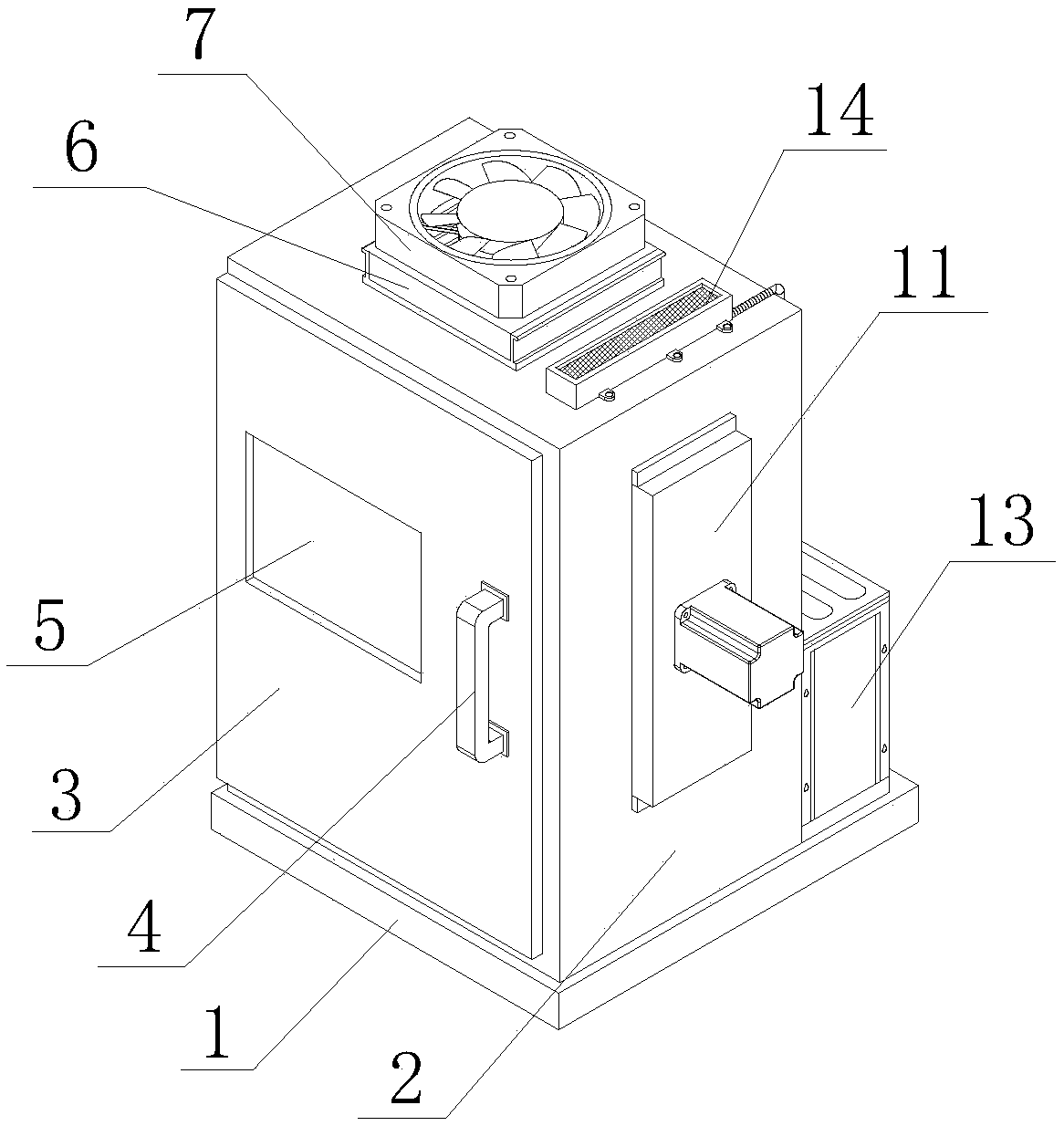
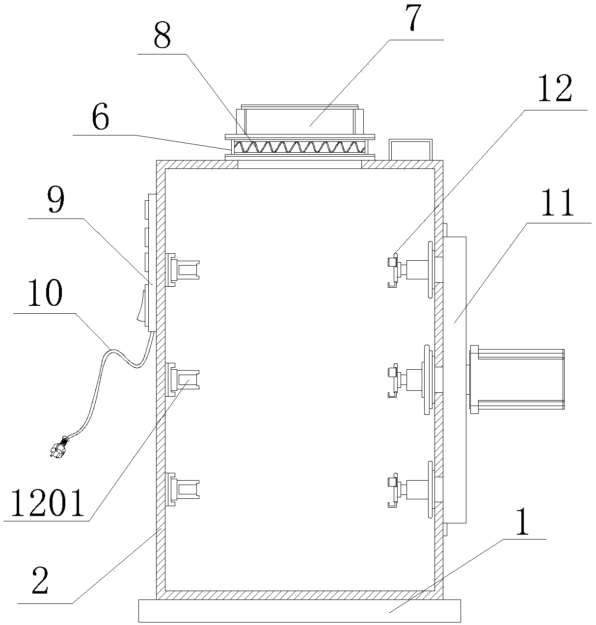
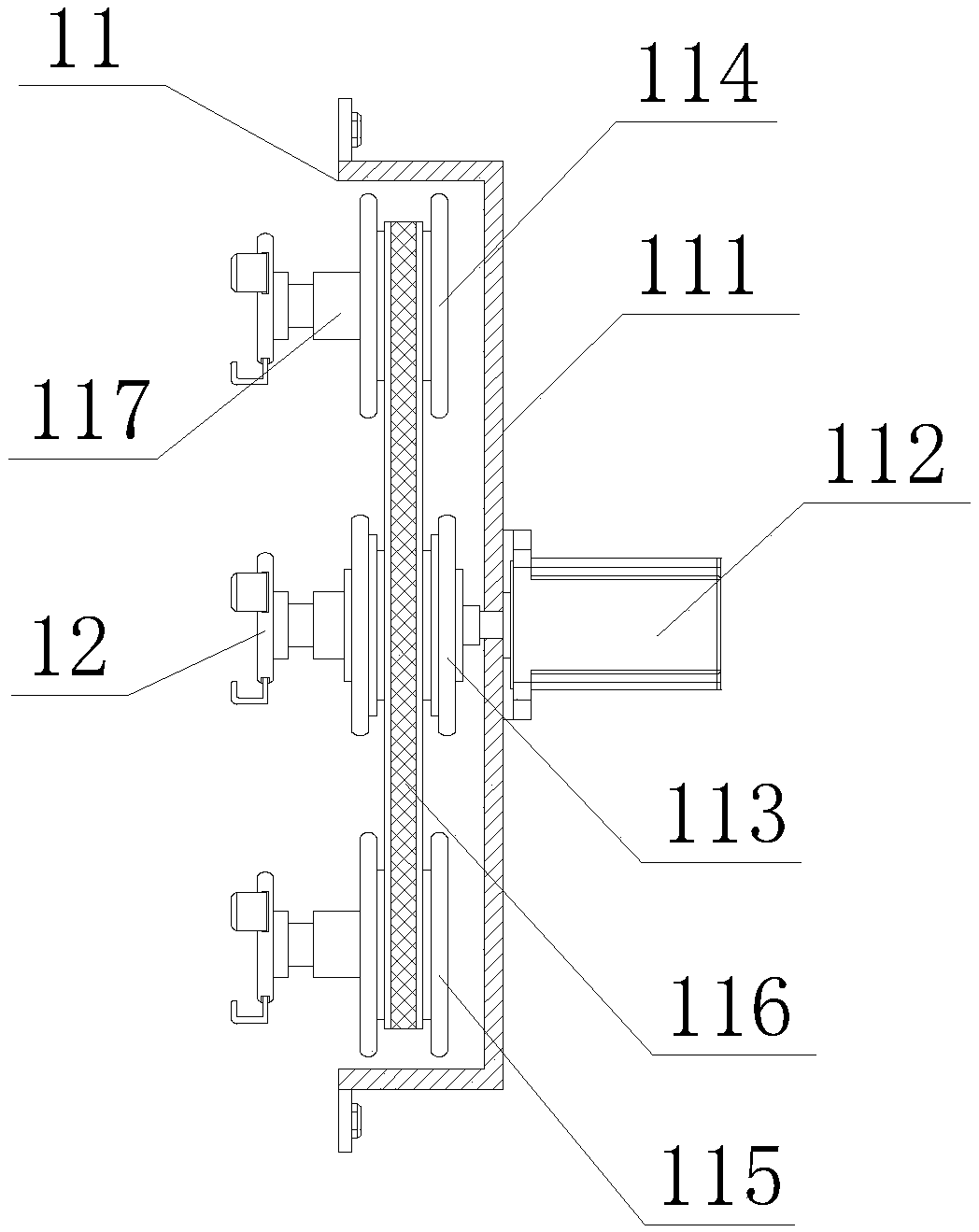
[0050] The present invention provides a drying device for textile printing and dyeing through improvement, including a support base 1, a drying box body 2, a box door 3, a door handle 4, an observation window 5, a heating box 6, a blower 7, and a heating wire 8. Control panel 9, power cord 10, rotating mechanism 11, clamping mechanism 12, cooling device 13 and purification device 14, the bottom of the drying box 2 is installed on the front side of ...


PUM

PropertyMeasurementUnit
thicknessaaaaaaaaaa

Abstract

The invention discloses a drying device for fabric printing and dyeing. The drying device comprises a support base, a drying tank, a tank door, a door handle, an observation window, a heating tank, anair blower, electric heating wires, a control panel, a power supply wire, a rotating mechanism, a clamping mechanism, a cooling device and a purification device, wherein the bottom of the drying tankis mounted on the front side of the upper end of the support base through bolts; the tank door is arranged at the front end of the drying tank; the left end of the tank door is rotationally connectedwith the drying tank through a hinge chain. Due to adoption of the rotating mechanism, when a motor is powered on, the driving wheel is driven by a front end output shaft to rotate, transmission is carried out through a transmission belt, meanwhile, a first driven wheel and a second driven wheel are driven to rotate, then a shaft base welded at the left end is rotated, the right end of the clamping mechanism is inserted into the shaft base, a fabric printing and dyeing article can be dried in a rotational manner, and the problems that a conventional drying device is single in drying directionof the fabric printing and dyeing article, non-uniform in drying, slow in drying speed and low in efficiency can be solved.

Description

technical field [0001] The invention relates to the related field of textile printing and dyeing drying equipment, in particular to a drying device for textile printing and dyeing. Background technique [0002] The original meaning of textile is taken from the general term of spinning and weaving, but with the continuous development and improvement of the textile knowledge system and subject system, especially after the emergence of non-woven textile materials and three-dimensional composite weaving technologies, the current textile is not only a traditional Hand spinning and weaving also include garment, industrial and decorative textiles produced by non-woven technology, modern three-dimensional weaving technology, and modern electrostatic nano-netting technology. Therefore, modern textile refers to a multi-scale structure processing technology of fibers or fiber aggregates. With the development of society, the current textile products need to be dried after textile printi...

Claims


Application Information

Patent Timeline
Patent Type & Authority Applications(China)
IPC IPC(8): D06B15/00B01D46/12B01D53/04
CPCB01D46/0028B01D46/0036B01D46/12B01D53/0407D06B15/00B01D2267/60B01D2267/40B01D2257/93B01D2257/708B01D46/64
Inventor 范雄亮
Owner 泉州智驰自动化机械有限公司
Why Eureka
Try Eureka