Light source module

A light source module and light source technology, applied in the direction of light source, light source fixation, semiconductor devices of light-emitting elements, etc., can solve the problems of poor mechanical stability, complex structure, and inability to achieve light concentration, and achieve electrical stability, convenient installation, and heat dissipation Design scientific and reasonable effects

Active Publication Date: 2019-04-12
明朔(北京)电子科技有限公司 +1
View PDF6 Cites 0 Cited by
  • Summary
  • Abstract
  • Description
  • Claims
  • Application Information

AI Technical Summary

Problems solved by technology

[0007] The most effective way to obtain an axially asymmetric illumination pattern is to tilt the luminaire; the problem is that the mechanical stability is poor and the spotlight cannot be achieved
Another implementation method is to use a lens array; the problem is that the structure is complex and requires the assembly of discontinuous optical surfaces
Therefore, current state-of-the-art techniques are not ideal for generating asymmetric illumination patterns

Method used


Image

  • Light source module
  • Light source module
  • Light source module

Examples


Embodiment

[0056] Stakeout and Fabrication of Lens

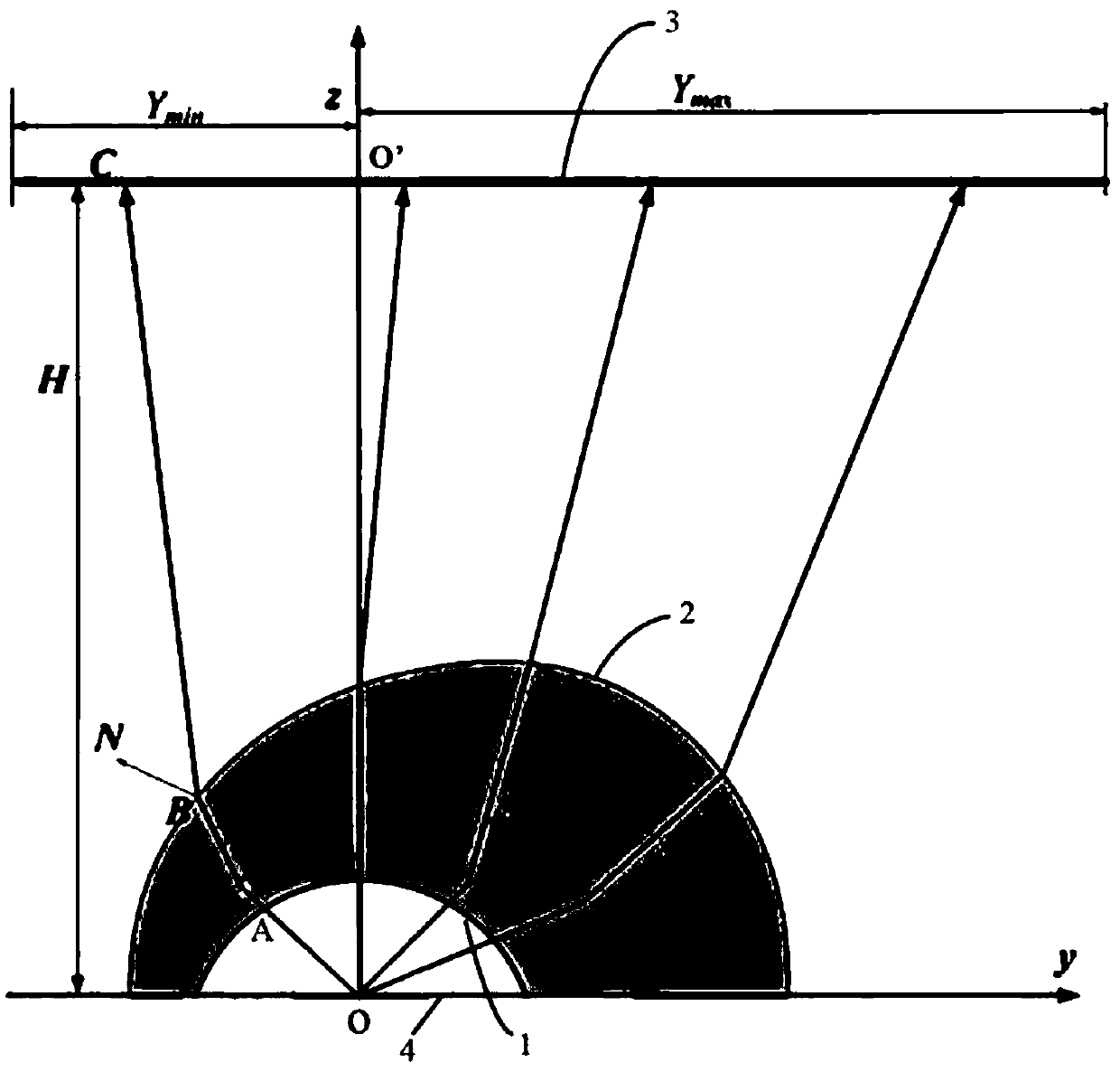
[0057] Such as figure 1 As shown, in the manufacturing process, the following method is used to determine the shape of the convex surface 2 when the size of the lens (the height of the spherical surface formed by the concave surface is 3cm) and the internal concave surface 1 is known (for a hemisphere) Coordinate information: preset irradiating surface 3, the irradiating surface 3 is parallel to the first plane 4, the first plane 4 is the light-emitting surface determined by the edge line of the concave surface 1 of the lens; the irradiating surface 3 and the The vertical distance of the first plane 4 is 3 meters.

[0058] Establish a coordinate system with the center of the hemisphere determined by the concave surface 1 as the coordinate origin O, wherein the plane where the first plane is located is set as the xoy plane, wherein the x-axis and the y-axis are orthogonal to each other, passing through the origin O And the axis perpen...


PUM


Abstract

The invention provides an LED light source module. The LED light source module comprises a lens, a sunflower heat sink and a COB light source, wherein the structure of the lens is obtained by computing parameters of points on a spherical surface and an optical free-form surface inside the lens through a geometrical optical mapping algorithm. Compared with the prior art, the lens has the advantagethat the lens can obtain higher irradiation uniformity.

Description

technical field [0001] The invention belongs to the technical field of LED packaging; in particular, it relates to an LED light source module, which can well ensure the uniformity of illumination and improve the utilization efficiency of light, so that the light can irradiate the entire road and roadside areas to the maximum extent. Background technique [0002] LED (Light Emitting Diode) is a semiconductor light-emitting device based on the principle of P-N junction electroluminescence. It has the advantages of high electro-optic conversion efficiency, long service life, environmental protection and energy saving, and small size. It is known as the 21st century green lighting source. If it can be applied to the field of traditional lighting, it will have a very significant energy-saving effect, which is of great significance in today's increasingly tense global energy sources. With the breakthrough of the third-generation semiconductor material technology represented by nit...

Claims


Application Information

Patent Timeline
Patent Type & Authority Applications(China)
IPC IPC(8): F21K9/20F21V5/04F21V17/12F21V19/00F21V29/71F21V29/77F21V29/85F21V29/87F21V31/00F21Y115/10
CPCF21K9/20F21V5/04F21V17/12F21V19/001F21V29/71F21V29/77F21V29/85F21V29/87F21V31/00F21Y2115/10
Inventor 陈威周明新周丽彬
Owner 明朔(北京)电子科技有限公司
Why Eureka
Try Eureka