
Method for researching phase transition of a sample under high pressure

A sample and high-pressure technology, which is applied in the field of material research, can solve the problems that affect the heating efficiency of the device, optical resolution, poor achromatic lens effect, parameter optimization limitations, etc., and achieve the effect of small chromatic aberration, accurate determination, and high resolution

Active Publication Date: 2019-04-12
JINHUA VOCATIONAL TECH COLLEGE
View PDF6 Cites 0 Cited by
  • Summary
  • Abstract
  • Description
  • Claims
  • Application Information

AI Technical Summary

Problems solved by technology

[0002] Currently, in the field of studying the phase transition of samples under high pressure, the prior art defect 1: There are usually two methods for studying the melting process of samples in the prior art. One method is to directly observe the change of the optical image of the sample before heating and after cooling ; One method is to use the laser to enter the heating area while heating the sample, and observe the changes of the speckle interference image formed by the reflection of the sample to the laser. Both of these methods lack quantitative characterization to obtain the actual melting of the sample Temperature, in this method, in the prior art, the heating laser and the imaging laser are usually incident on the sample with the same optical path, so the optimization of some parameters in the optical path will be limited, which will affect the heating efficiency and optical resolution of the device; the existing technology Defect 2: In the temperature measurement of the sample, it is necessary to collect the light reflected from the surface of the sample, so it is necessary to minimize the chromatic aberration in the optical path. The standard achromatic lens used in the prior art is not effective, and the temperature above 1000K Significant errors can be introduced into temperature measurements, depending on the size of the heated region on the sample, which can be resolved by a method for studying the phase transition of samples under high pressure

Method used


Image

  • Method for researching phase transition of a sample under high pressure

Examples


Embodiment Construction

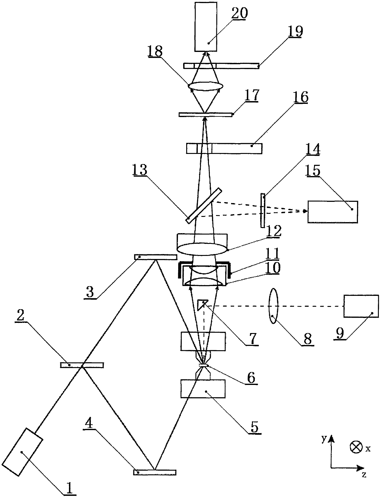
[0031] Such as figure 1 It is a schematic diagram of the present invention, including laser I (1), beam splitter I (2), mirror I (3), mirror II (4), sapphire anvil (5), sample (6), prism (7) , lens I (8), laser II (9), dephaser lens group (10), aperture (11), objective lens (12), beam splitter II (13), filter (14), video camera (15), Chopper (16), aperture diaphragm (17), lens II (18), optical filter group (19) and detector (20), the laser light that laser device I (1) emits is heating laser, laser device II (9) The emitted laser is an imaging laser, and the incident optical path of the heating laser, the incident optical path of the imaging laser, the thermal radiation path and the visible light path emitted by the sample, xyz is a three-dimensional Cartesian coordinate system; the sapphire anvil (5) includes the upper top Anvil and lower anvil, sample (6) is located between said upper anvil and lower anvil, sample (6) is a circle with a typical size of three millimeters in ...


PUM

PropertyMeasurementUnit
diameteraaaaaaaaaa
diameteraaaaaaaaaa

Abstract

The invention relates to the field of materials research and provides a method for researching the phase transition of a sample under high pressure. An apparatus for researching the phase transition of a sample at high pressure comprises a laser I, a beam splitter I, a mirror I, a mirror II, a sapphire anvil, the sample, a prism, a lens I, a laser II, a lens group for eliminating phase difference,an aperture, an objective lens, a beam splitter II, an optical filter, a camera, a chopper, a pinhole diaphragm, a lens II, an optical filter set and a detector. By means of a laser heating and optical image analysis method, the heating laser and the imaging laser are respectively incident on the sample by different optical paths, the heating efficiency of the sample and the collection efficiencyof reflected light can be optimized, and the method of combining an achromatic lens with the pinhole diaphragm is used to reduce the chromatic aberration in the optical paths, improve the resolutionof the thermal radiation spectrum measured by the detector, and improve the measurement accuracy of the sample temperature. The melting temperature of the sample can be determined more accurately by quantitatively analyzing the speckle interference pattern reflected from the sample surface by two methods.

Description

technical field [0001] The invention relates to the field of material research, in particular to a method for studying the phase transition of a sample under high pressure, which determines the melting temperature of a sample under high pressure by means of laser heating and optical image analysis. Background technique [0002] Currently, in the field of studying the phase transition of samples under high pressure, the prior art defect 1: There are usually two methods for studying the melting process of samples in the prior art. One method is to directly observe the change of the optical image of the sample before heating and after cooling ; One method is to use the laser to enter the heating area while heating the sample, and observe the changes of the speckle interference image formed by the reflection of the sample to the laser. Both of these methods lack quantitative characterization to obtain the actual melting of the sample Temperature, in this method, in the prior art...

Claims


Application Information

Patent Timeline
Patent Type & Authority Applications(China)
IPC IPC(8): G01N25/04G01N25/20
CPCG01N25/04G01N25/20
Inventor 张向平方晓华赵永建
Owner JINHUA VOCATIONAL TECH COLLEGE
Learn More