
AR-based pipe network visualization system

A pipe network and screen technology, applied in the field of AR-based pipe network visualization system, can solve the problems of low inspection efficiency and memory capacity occupation, and achieve the effect of avoiding modeling workload, small network bandwidth, and low memory requirements.

Active Publication Date: 2019-04-12
重庆予胜远升网络科技有限公司 +1
View PDF5 Cites 6 Cited by
  • Summary
  • Abstract
  • Description
  • Claims
  • Application Information

AI Technical Summary

Problems solved by technology

[0008] The purpose of the present invention is to provide an AR-based pipeline network visualization system, which can avoid the problems of serious memory capacity occupation and low inspection efficiency caused by the pre-built 3D model of the existing AR visualization system

Method used


Image

  • AR-based pipe network visualization system
  • AR-based pipe network visualization system

Examples


Embodiment 1

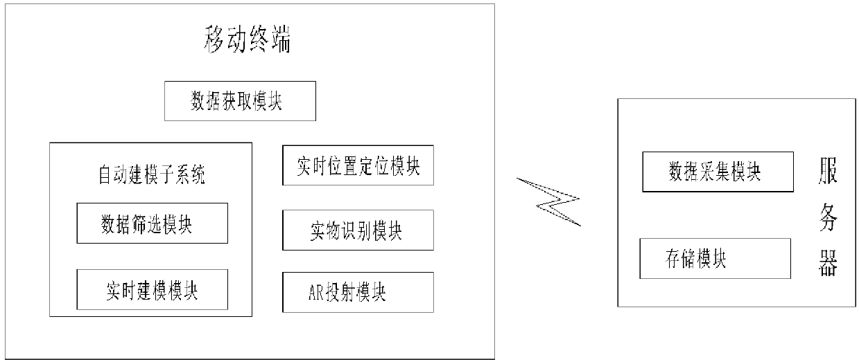
[0030] Such as figure 1 Shown: An AR-based pipeline network visualization system, including a server and a mobile terminal worn by inspectors. The mobile terminal and server are connected through the existing wireless communication module network.

[0031] 1. Servers, including:

[0032] The data collection module is used to collect big data of the pipe network, which includes digital information of the pipe network and monitoring data of the pipe network.

[0033] Pipe network digital information includes pipeline data, pipeline network construction design blueprint and two-dimensional electronic pipeline map. Pipeline data includes buried direction, buried depth, latitude and longitude coordinates, pipe diameter size and pipeline information. Natural gas pipeline), the street to which it belongs, the department and other information; the two-dimensional plane electronic pipeline map is drawn from centimeter-level GNSS positioning and pipeline data.

[0034] Pipe network mo...

Embodiment 2

[0050] Compared with Embodiment 1, this embodiment differs only in that this embodiment also includes a disaster prediction subsystem.

[0051] In recent years, earthquake disasters have occurred frequently, and earthquakes will seriously affect the normal work of the pipeline network. Most of the pipeline network is buried deep underground, so it is difficult to know the working status of the pipeline network, and it is also difficult to judge the status of the pipeline network only based on changes on the surface. In the prior art, Internet of Things detectors, leakage sensors, etc. are used to monitor various data in the pipeline network in real time, and when the data is abnormal, the pipeline network failure is judged. Although the above method is accurate in judgment, it lacks pertinence and predictability: First, the inspectors cannot see the actual situation of the pipeline network, and cannot determine the key inspection areas. ;Secondly, the inspectors need to know ...


PUM


Abstract

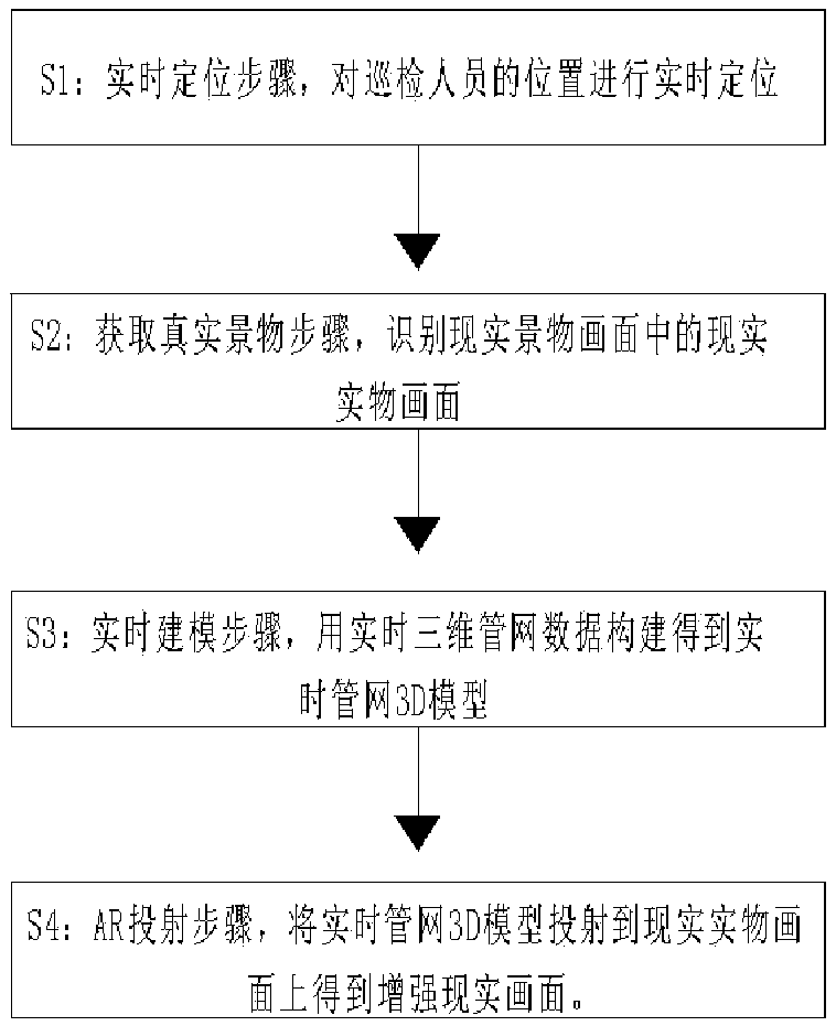
The invention relates to the technical field of augmented reality, in particular to an AR-based pipe network visualization system which comprises a real object recognition module used for collecting areal scene picture, obtaining the real-time position of an inspector and recognizing the real scene picture from the real scene picture according to the real-time position; the data screening moduleis used for acquiring the pipe network big data and the real-time position of the inspection personnel, and screening the pipe network big data according to the real-time position to obtain real-timepipe network data; the real-time modeling module is used for acquiring real-time pipe network data, generating real-time three-dimensional pipe network data from the real-time pipe network data and constructing the real-time three-dimensional pipe network data into a real-time pipe network 3D model; and the AR projection module is used for acquiring the real-time pipe network 3D model and the real-time object picture and projecting the real-time pipe network 3D model to the real-time object picture to obtain an augmented reality picture. According to the invention, the problems of serious memory capacity waste and low inspection efficiency caused by pre-construction of a 3D model in the existing AR visualization system can be solved.

Description

technical field [0001] The invention relates to the field of augmented reality technology, in particular to an AR-based pipe network visualization system and method. Background technique [0002] All kinds of underground pipe networks in cities are an important part of urban infrastructure. They are like nerves and blood vessels in the human body. They are responsible for transmitting information and energy day and night. They are the material basis for the survival and development of cities. They are called The lifeline of the city. In recent years, my country's urban construction has developed rapidly. The original underground pipe network in the city can no longer meet the needs of modern development. The renewal of the old pipe network, the design and construction of the new pipe network, and the planning of the new pipe network all need accurate Master the status of the underground pipe network. [0003] The management of the underground pipe network mainly has the fol...

Claims


Application Information

Patent Timeline
Patent Type & Authority Applications(China)
IPC IPC(8): G06T19/00G06T17/05G06Q50/26
CPCG06Q50/26G06T17/05G06T19/006Y02A10/40
Inventor 谭利辉
Owner 重庆予胜远升网络科技有限公司
Learn More