
Waste separation device for high-density graphite engraving and milling machine

A separation device, engraving and milling machine technology, used in dryers, transportation and packaging, stone processing equipment and other directions, can solve the problems of inability to clean workpieces and fixed plates, inability to adjust the angle of workpieces well, and inability to separate waste materials, etc. Achieve the effect of delaying corrosion time, reducing cleaning times, and facilitating centralized treatment

Pending Publication Date: 2019-04-16
屈晓芳
View PDF8 Cites 0 Cited by
  • Summary
  • Abstract
  • Description
  • Claims
  • Application Information

AI Technical Summary

Problems solved by technology

[0003] An engraving and milling machine disclosed in the Chinese Invention Patent Application Publication CN102773529AU, although the engraving and milling machine has a reasonable structure, is safe and reliable, and is convenient for wiring, but the engraving and milling machine cannot adjust the angle of the workpiece well and cannot Measuring the distance between the engraving and milling machine and the workpiece cannot clean the workpiece and the fixed plate well, separate the waste materials well, recycle the sewage well, and reduce the carving The dust inside the milling machine cannot prevent the wire bundles from being entangled with each other

Method used


Image

  • Waste separation device for high-density graphite engraving and milling machine
  • Waste separation device for high-density graphite engraving and milling machine
  • Waste separation device for high-density graphite engraving and milling machine

Examples


Embodiment Construction

[0028] The following will clearly and completely describe the technical solutions in the embodiments of the present invention with reference to the accompanying drawings in the embodiments of the present invention. Obviously, the described embodiments are only some, not all, embodiments of the present invention.

[0029] In the description of the present invention, unless otherwise stated, the meaning of "plurality" is two or more; the terms "upper", "lower", "left", "right", "inner", "outer" , "front end", "rear end", "head", "tail", etc. indicate the orientation or positional relationship based on the orientation or positional relationship shown in the drawings, and are only for the convenience of describing the present invention and simplifying the description, rather than Nothing indicating or implying that a referenced device or element must have a particular orientation, be constructed, and operate in a particular orientation should therefore not be construed as limiting ...


PUM


Abstract

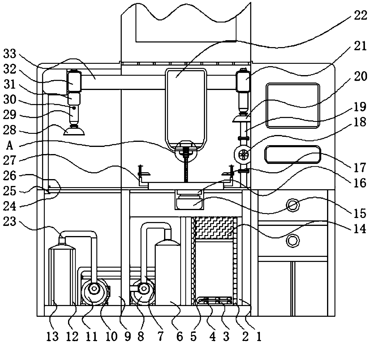
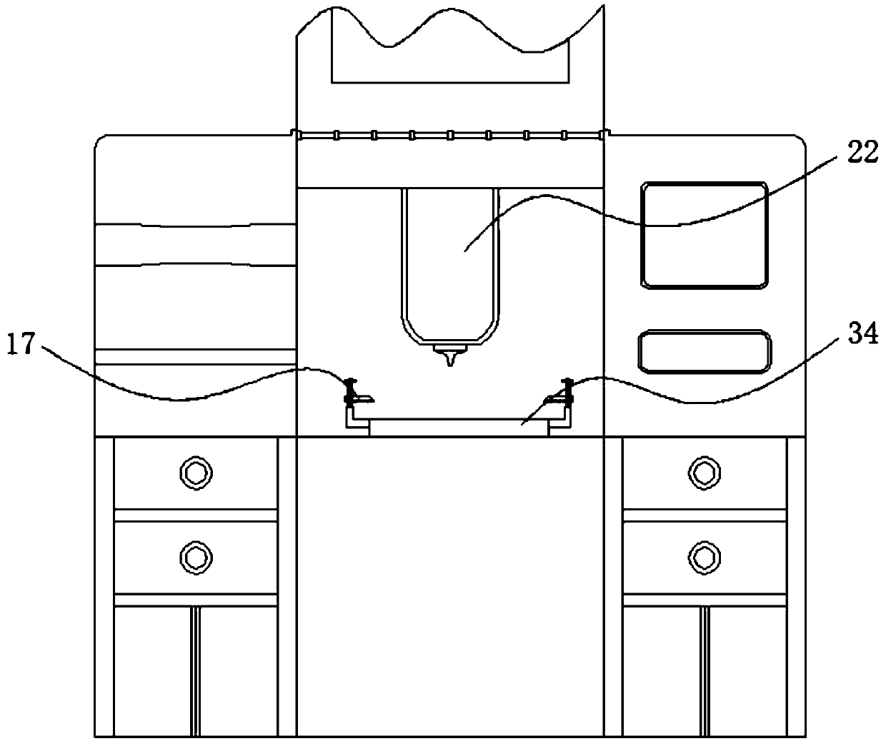
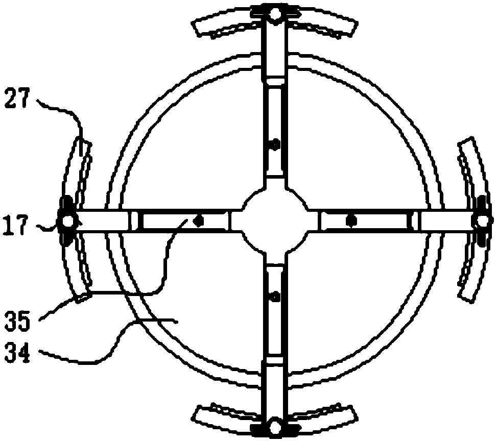
The invention relates to the technical field of engraving and milling machines, in particular to a waste separation device for a high-density graphite engraving and milling machine. The waste separation device for the high-density graphite engraving and milling machine comprises a stainless steel shell, a stopping block and a PP filter core, wherein the stainless steel shell is fixedly connected with the stopping block, and the vertical center line of the stainless steel shell is parallel to the PP filter core; and dust suction cotton is arranged in the stainless steel shell, a wire harness groove is formed in the dust suction cotton, a pin shaft is arranged in the stopping block, the stopping block is arranged in the middle of the wire harness groove, and the stopping block is connected with the wire harness groove in a pin joint mode through the pin shaft. According to the waste separation device for the high-density graphite engraving and milling machine, a filter net can effectively separate waste from sewage, the waste is collected through the filter net, a sewage pool provides storage space for the filtered sewage, and a user conveniently treats the sewage in the sewage poolcentrally.

Description

technical field [0001] The invention relates to the technical field of engraving and milling machines, in particular to a waste separation device for high-density graphite engraving and milling machines. Background technique [0002] Engraving and milling machine is a kind of CNC machine tool. It is generally believed that engraving and milling machine is a CNC milling machine that uses small tools, high power and high-speed spindle motor. The appearance of the engraving and milling machine can be said to fill the gap between the two. The engraving and milling machine can be used for both engraving and milling. It is an efficient and high-precision CNC machine tool. The concept of the engraving and milling machine was first proposed and realized by Jiatie. The scope of application of the milling machine is relatively wide. It is widely used in the rough and fine machining of the precision mold core, the copper electrode of the mold, the batch processing of aluminum products,...

Claims


Application Information

Patent Timeline
Patent Type & Authority Applications(China)
IPC IPC(8): B09B3/00F26B21/00C02F9/02B28D1/18B28D7/00B28D7/02B28D7/04
CPCF26B21/001F26B21/004C02F1/001C02F1/281B28D1/18B28D7/00B28D7/02B28D7/04C02F2303/02B09B3/00B09B2101/02
Inventor 屈晓芳
Owner 屈晓芳
Learn More