Electronic control diagnosing engine water temperature system and method

An engine water temperature, electronic control technology, applied in engine components, engine cooling, machine/engine and other directions, can solve problems such as engine abnormality, cooling system failure, engine failure, etc., to meet fuel consumption and emission requirements, and avoid engine damage. , the effect of solving uncontrollable factors

Inactive Publication Date: 2019-04-16
ZHEJIANG YILI AUTO PARTS CO LTD +1
View PDF8 Cites 1 Cited by
  • Summary
  • Abstract
  • Description
  • Claims
  • Application Information

AI Technical Summary

Problems solved by technology

[0005] During the normal use and maintenance of the car, the coolant needs to be supplemented regularly and quantitatively. If the owner does not replenish the coolant in time, the coolant in the engine will be too little, and the cooling system will fail, which will lead to engine failure.
In addition, the traditional engine only has a water temperature sensor on the cylinder head of the main cycle of the engine. This sensor can only detect the water temperature of the water outlet of the engine cylinder head, and cannot detect the water temperature of the large cycle, heating cycle water temperature, supercharger cooling cycle water temperature, and oil cooling. The circulating water temperature of the engine and the cooling circulating water temperature of the automatic transmission; the ideal coolant filling volume of the engine is certain, too much or too little engine oil will cause the engine to be abnormal, and only a certain range of the coolant volume can be monitored through the scale line of the filling pot. However, it is impossible to accurately control the amount of coolant in the engine; the flow distribution of the small engine cycle, the large cycle, and the auxiliary cycle requires different amounts under different loads and speeds. At present, once the cooling system of the traditional engine is designed, there is only one temperature control. controller and a water temperature sensor, the flow distribution is fixed and cannot be automatically adjusted according to the actual operating conditions

Method used


Image

  • Electronic control diagnosing engine water temperature system and method

Examples


Embodiment Construction

[0028] The present invention will be further described below in conjunction with the accompanying drawings and examples.

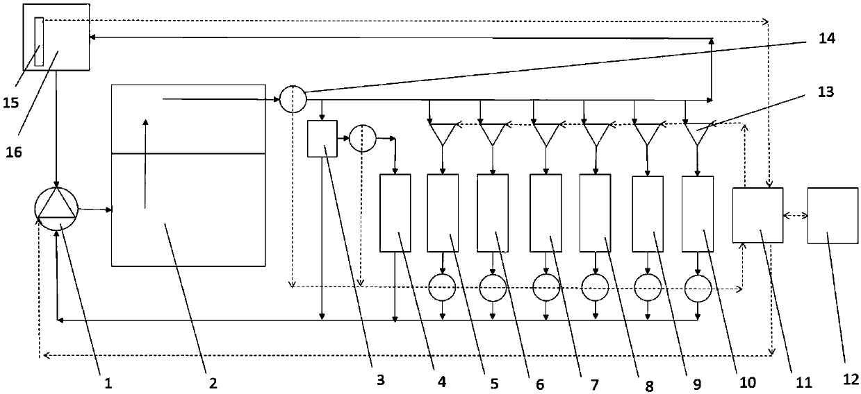
[0029] Such as figure 1 As shown, an electronically controlled diagnosis engine water temperature system includes ECU11, a cooling circulation loop and a plurality of cooling bodies located on the cooling circulation loop, the cooling circulation loop passes through the plurality of cooling bodies, and the cooling circulation loop is distributed with A plurality of detection devices and a plurality of flow control devices for sensing the state of the cooling body, and a plurality of detection devices and a plurality of flow control devices are connected to the ECU11, and the ECU11 controls a plurality of flow control by receiving and processing information from a plurality of detection devices Device action.

[0030] In this embodiment, the control device is an electronic throttle valve 13, a plurality of detection devices include a plurality of temperatu...


PUM


Abstract

The invention discloses an electronic controldiagnosing engine water temperature system and method. Theelectronic control diagnosing engine water temperature system comprises an ECU, a cooling circulation loop and a plurality of cooling bodies located on the cooling circulation loop, the cooling circulation loop passes through the cooling bodies, a plurality of detecting devices for sensing the state of the cooling bodies and a plurality of flow control devices are distributed on the cooling circulation loop,and the detecting devices and the flow control devices are connected with the ECU; andthe ECU controls the flow control devices to act by receiving and processing information of detecting devices. A control device is used for controlling to form a complete electronic control loop;andthe water flow is reasonably distributed according to different working loads and rotational speeds of an engine, the water temperature is displayed in a user interface in real time,if an abnormalityoccurs, an alarm can be timely given, and safety of vehicle driving can be guaranteed.

Description

technical field [0001] The invention relates to automobile cooling, in particular to an electronic control system and method for diagnosing engine water temperature. Background technique [0002] The function of the engine cooling system is to dissipate part of the heat absorbed by the heated parts in time to ensure that the engine works at the most suitable temperature state. The cooling system of the engine is divided into air-cooled and water-cooled. The cooling system that uses air as the cooling medium is an air cooling system; the cooling system that uses cooling liquid as the cooling medium is called a water cooling system. [0003] The cooling system of the automobile engine is a forced circulation water cooling system, that is, the water pump is used to increase the pressure of the coolant, and the coolant is forced to circulate in the engine. The cooling system is mainly composed of water pumps, radiators, cooling fans, compensation water tanks, thermostats, engi...

Claims


Application Information

Patent Timeline
Patent Type & Authority Applications(China)
IPC IPC(8): F01P3/20F01P7/14F01P11/16H02K9/193
CPCF01P3/20F01P7/14F01P11/16F01P2007/146F01P2060/04F01P2060/045F01P2060/08F01P2060/12H02K9/193
Inventor 邱若友潘建考尹建东沈源王瑞平
Owner ZHEJIANG YILI AUTO PARTS CO LTD
Why Eureka
Try Eureka