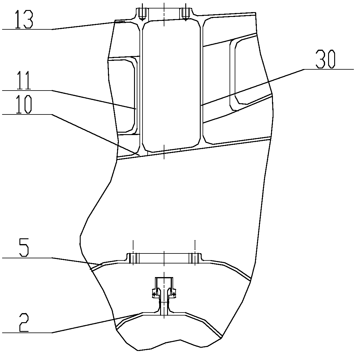
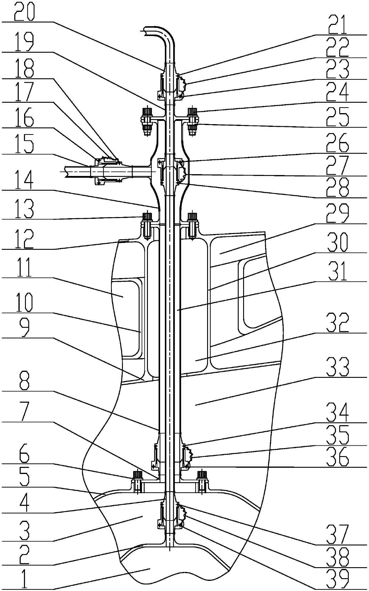
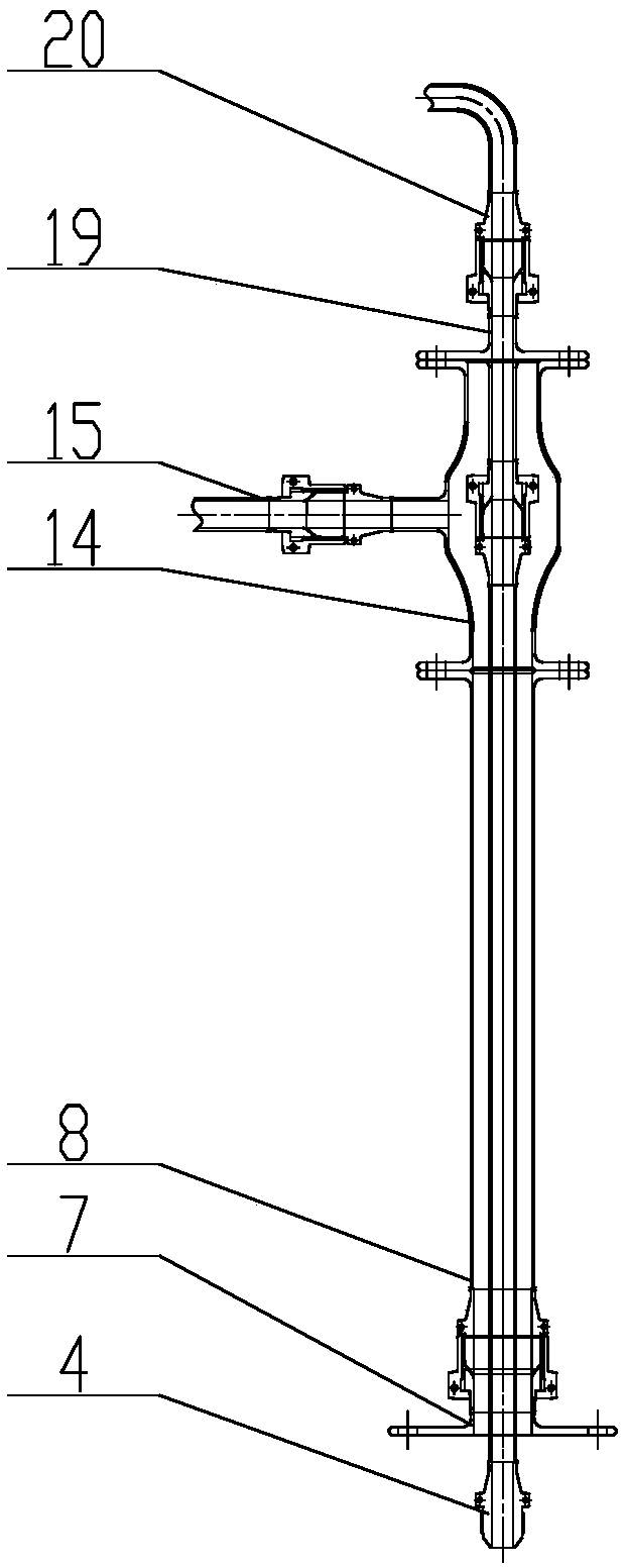
Thermal protection structure of oil-gas mixture for aero-engine

A technology of oil-air mixture and thermal protection structure, which is applied in the direction of engine components, machine/engine, engine lubrication, etc., can solve the problems of weakening the running time of aero-engines, increasing the oil consumption of the whole machine, and adjusting the axial force of high-pressure rotors Weak capacity and other problems, to achieve the effect of eliminating the risk of oil and gas coking and deflagration, high structural reliability, and small thickness requirements

Active Publication Date: 2019-04-16
AECC SHENYANG ENGINE RES INST
View PDF7 Cites 5 Cited by
  • Summary
  • Abstract
  • Description
  • Claims
  • Application Information

AI Technical Summary

Problems solved by technology

[0002] In the prior art, the oil-gas ventilation pipe is also arranged in the load-bearing support plate, and the temperature of the gas circulating in the support plate is relatively lower, which will not cause coking of the oil-gas mixture. If the existing technical solution is directly applied, the disadvantages are: technically, the temperature Relatively low gas, its pressure is also relatively low, and it is impossible to seal the high-pressure main gas at the outlet of the high-pressure turbine. At the same time, because of its low pressure, its ability to adjust the axial force of the high-pressure rotor is weak, and it cannot meet the technical requirements of the aero-engine. Functional requirements; In terms of cost, if the existing technical solution is adopted, the oil-gas mixture will coke due to overheating, and the coking of oil and gas will cause many hazards. After the coke layer accumulates and falls off, it will block the pipeline and centrifugal ventilator, resulting in the consumption of lubricating oil in the whole machine In terms of efficiency, oil and gas coking layer falls off, clogging pipelines and centrifugal ventilators will reduce the efficiency of oil and gas separation of aeroengines; in terms of safety, if pipelines are damaged, support Plate cracking and rectifying guide vane sealing degradation lead to high-temperature gas in the main channel coming into contact with the oil-gas mixture in the ventilation pipe, which will cause the risk of oil-gas deflagration, which will cause the aero-engine to lose its working ability and endanger flight safety

Method used


Image

  • Thermal protection structure of oil-gas mixture for aero-engine
  • Thermal protection structure of oil-gas mixture for aero-engine
  • Thermal protection structure of oil-gas mixture for aero-engine

Examples


Embodiment Construction

[0035] The application will be further described in detail below in conjunction with the accompanying drawings and embodiments. It should be understood that the specific embodiments described here are only used to explain the related application, not to limit the application. In addition, it should be noted that, for ease of description, only parts relevant to the present application are shown in the drawings.

[0036] It should be noted that, in the case of no conflict, the embodiments in the present application and the features in the embodiments can be combined with each other. The present application will be described in detail below with reference to the accompanying drawings and embodiments.

[0037] It should be noted that in the description of this application, the terms "center", "upper", "lower", "left", "right", "vertical", "horizontal", "inner", "outer", etc. The terms of the indicated direction or positional relationship are based on the direction or positional ...


PUM


Abstract

The invention provides a thermal protection structure of an oil-gas mixture for an aero-engine. The thermal protection structure of the oil-gas mixture for the aero-engine comprises an oil-gas ventilation pipeline assembly inside a support plate, a sealing cavity outer casing adaptor seat, a sealing air guiding pipe assembly inside the support plate, a two-way ventilation adaptor, an exterior oil-gas ventilation welded assembly, a split bi-functional assembly, and an exterior sealing air guiding pipe assembly.

Description

technical field [0001] The application relates to the technical field of aero-engines, and specifically provides a thermal protection structure for oil-air mixtures used in aero-engines. Background technique [0002] In the prior art, the oil-gas ventilation pipe is also arranged in the load-bearing support plate, and the temperature of the gas circulating in the support plate is relatively lower, which will not cause coking of the oil-gas mixture. If the existing technical solution is directly applied, the disadvantages are: technically, the temperature Relatively low gas, its pressure is also relatively low, and it is impossible to seal the high-pressure main gas at the outlet of the high-pressure turbine. At the same time, because of its low pressure, its ability to adjust the axial force of the high-pressure rotor is weak, and it cannot meet the technical requirements of the aero-engine. Functional requirements; In terms of cost, if the existing technical solution is ado...

Claims


Application Information

Patent Timeline
Patent Type & Authority Applications(China)
IPC IPC(8): F02C7/00F02C7/06F02C7/20
CPCF02C7/00F02C7/06F02C7/20
Inventor 怀时卫徐雪张德志徐朋飞
Owner AECC SHENYANG ENGINE RES INST
Why Eureka
Try Eureka