Wide-range swirling pulverized coal burner adopting flue gas recirculation for industrial pulverized coal boiler

A technology of flue gas recirculation and pulverized coal burner, which is applied in the direction of burning powder fuel, burning block fuel and gaseous fuel, burning liquid fuel and gaseous fuel, etc., and can solve fly ash combustibles High content, easy slagging in the furnace, high NOx emissions, etc., to avoid slagging and high-temperature corrosion in the furnace, avoid a large amount of generation, and have a large contact area

Inactive Publication Date: 2019-04-16
HARBIN INST OF TECH
View PDF6 Cites 1 Cited by
  • Summary
  • Abstract
  • Description
  • Claims
  • Application Information

AI Technical Summary

Problems solved by technology

Although the above-mentioned technologies have reduced the NOx concentration to a certain extent, there are still common problems such as high NOx emissions, easy slagging in the furnace, and high content of fly ash combustibles.

Method used


Image

  • Wide-range swirling pulverized coal burner adopting flue gas recirculation for industrial pulverized coal boiler
  • Wide-range swirling pulverized coal burner adopting flue gas recirculation for industrial pulverized coal boiler

Examples


specific Embodiment approach 1

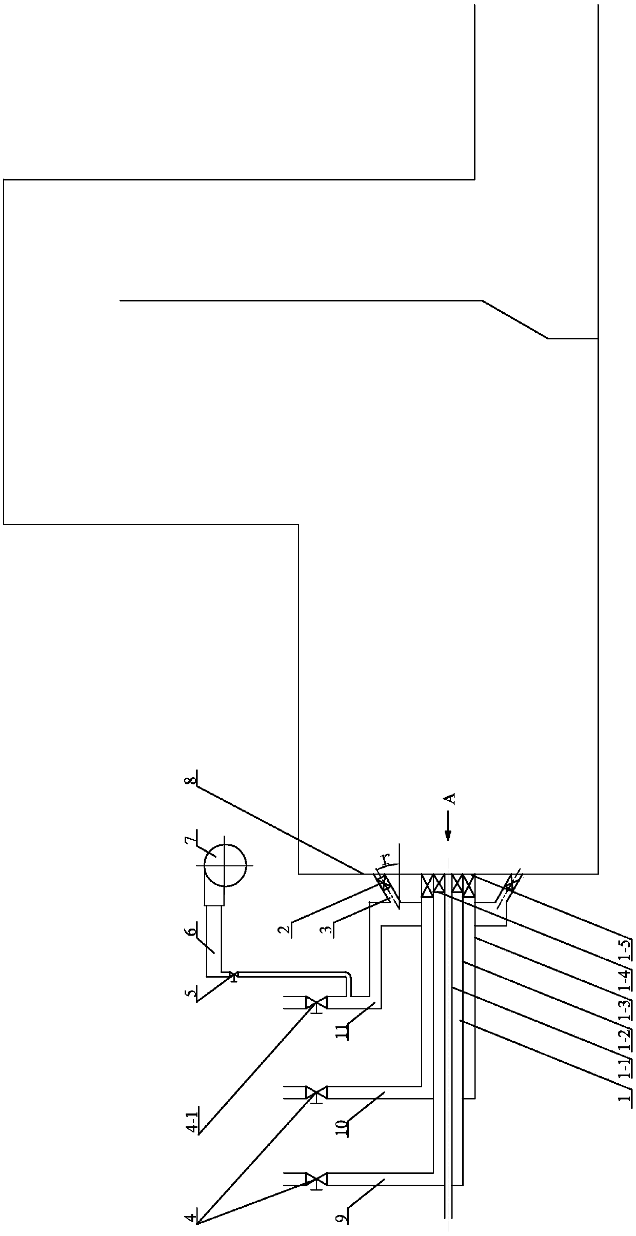
[0028] Specific implementation mode one: combine Figure 1-Figure 2 Describe this embodiment, the industrial pulverized coal boiler described in this embodiment adopts a wide adjustment ratio swirl pulverized coal burner for flue gas recirculation, which includes a swirl pulverized coal burner 1, a recirculation flue gas pipeline 6, and a recirculation fan 7. Separated secondary air air pipe valve 4-1, first burner secondary air air pipe 9, second burner secondary air air pipe 10, separated secondary air air pipe 11, two burner secondary air Air pipe valve 4, a plurality of separated secondary air nozzle pipes 2 and a plurality of separated secondary air swirlers 3; the first burner secondary air air pipe 9 and the second burner secondary air air pipe 10 are respectively installed There is a burner secondary air air pipeline valve 4, a separated secondary air air pipeline 11 is installed with a separated secondary air air pipeline valve 4-1, and the swirl pulverized coal burne...

specific Embodiment approach 2

[0029] Specific implementation mode two: combination figure 1 This embodiment is described. The industrial pulverized coal boiler in this embodiment adopts a swirl pulverized coal burner with a wide adjustment ratio of flue gas recirculation. Air duct 1-2, secondary air duct 1-3 outside the swirl flow, secondary air swirl blades 1-4 inside and secondary swirl blades 1-5 outside, primary air duct 1-1, secondary air flow inside the swirl flow The pipe 1-2 and the secondary air pipe 1-3 outside the swirling flow are set coaxially in sequence from the inside to the outside, and an internal secondary swirling flow is installed between the primary air pipe 1-1 and the secondary air pipe 1-2 inside the swirling flow Blades 1-4, outer secondary swirl blades 1-5 are installed between the swirl inner secondary air duct 1-2 and the swirl outer secondary air duct 1-3, the length value of the primary air duct 1-1, The length value of the secondary air pipe 1-2 in the swirl flow and the le...

specific Embodiment approach 3

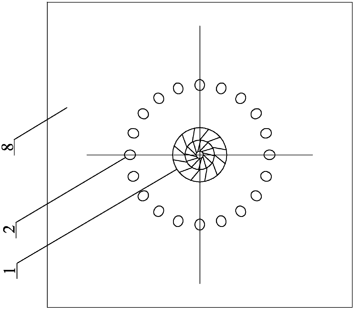
[0030] Specific implementation mode three: combination figure 1 Describe this embodiment, the industrial pulverized coal boiler described in this embodiment adopts a wide adjustment ratio swirl pulverized coal burner for flue gas recirculation, the primary air pipe 1-1, the secondary air pipe 1-2 in the swirl flow and the swirl flow A secondary air duct is respectively installed on the outer secondary air duct 1-3, and a plurality of separate secondary air ducts are evenly distributed and obliquely installed on the side wall of the secondary air duct located on the outer secondary air duct 1-3 of the swirling flow. The secondary air nozzle pipe 2, and a plurality of separated secondary air nozzle pipes 2 are arranged in a gradually expanding form from the secondary air air pipe to the boiler furnace front wall 8 of the horizontal boiler, and each separated secondary air nozzle pipe 2 The angle formed by the center line and the center line of the primary air duct 1-1 is r, and ...


PUM


Abstract

The invention discloses a wide-range swirling pulverized coal burner adopting flue gas recirculation for an industrial pulverized coal boiler, relates to a boiler swirling burner, and aims to solve the problems that as for a current industrial pulverized coal boiler, the NOx emission is high, a hearth is prone to being slagged, and the fly ash combustible matter content is high. The wide-range swirling pulverized coal burner comprises a swirling pulverized coal burner body, a recirculation flue gas pipeline, a recirculation fan, a separation secondary air pipeline valve, a first burner secondary air pipeline, a second burner secondary air pipeline, a separation secondary air pipeline, two burner secondary air pipeline valves, a plurality of separation secondary air nozzle pipes and a plurality of separation secondary air swirlers, the two burner secondary air pipeline valves are mounted on the first burner secondary air pipeline and the second burner secondary air pipeline correspondingly, a separation secondary air pipeline valve is mounted on the separation secondary air pipeline, and the swirling pulverized coal burner body is mounted at the center of a front wall of a boiler hearth of the horizontal boiler. The wide-range swirling pulverized coal burner is used for the field of boiler combustion.

Description

technical field [0001] The invention relates to a combined denitrification burner in a boiler main combustion area spraying a reducing agent, in particular to a swirl pulverized coal burner with a wide adjustment ratio that adopts flue gas recirculation in an industrial pulverized coal boiler, and belongs to the field of boilers. Background technique [0002] Coal-fired industrial boilers are the main coal-consuming equipment in my country except power plant boilers, with a total of nearly 600,000 units and an annual coal consumption of nearly 640 million tons. Coal-fired industrial boilers produce about 2 million tons of NOx per year, second only to coal-fired power plant boilers, and have become one of the most important sources of NOx pollutant emissions in my country. [0003] Most of the traditional coal-fired industrial boilers are chain furnaces that adopt fire bed combustion. Compared with the chain furnace, the pulverized coal boiler adopts the chamber combustion c...

Claims


Application Information

Patent Timeline
IPC IPC(8): F23C5/08F23C7/00F23C9/00F23D1/02
Inventor 陈智超严蓉袁振华曾令艳李争起
Owner HARBIN INST OF TECH
Why Eureka
Try Eureka