
Air conditioner outdoor unit and air conditioner

A technology for outdoor units and air-conditioning rooms, which is applied in the direction of compressors, refrigerators, and compressors with reversible cycle. , the effect of reducing disturbance and protecting the compressor

Active Publication Date: 2021-08-06
QINGDAO HAIER AIR CONDITIONING ELECTRONICS CO LTD +1
View PDF7 Cites 0 Cited by
  • Summary
  • Abstract
  • Description
  • Claims
  • Application Information

AI Technical Summary

Problems solved by technology

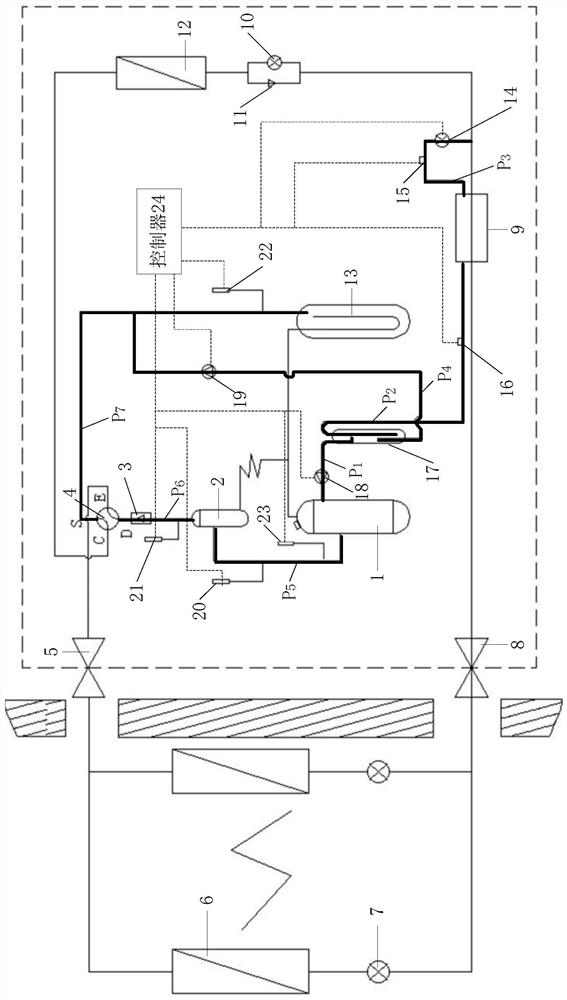
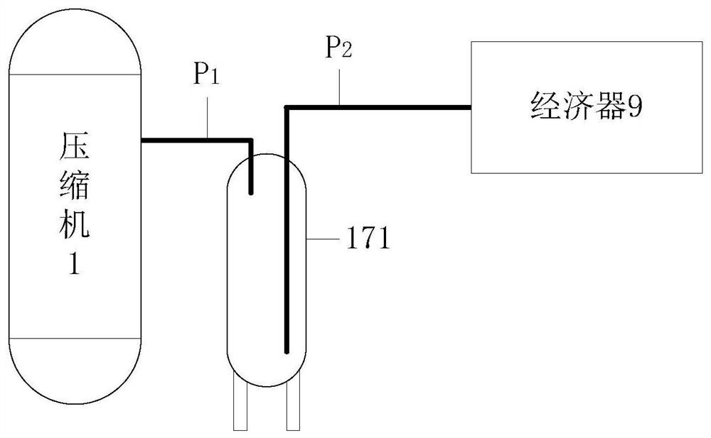
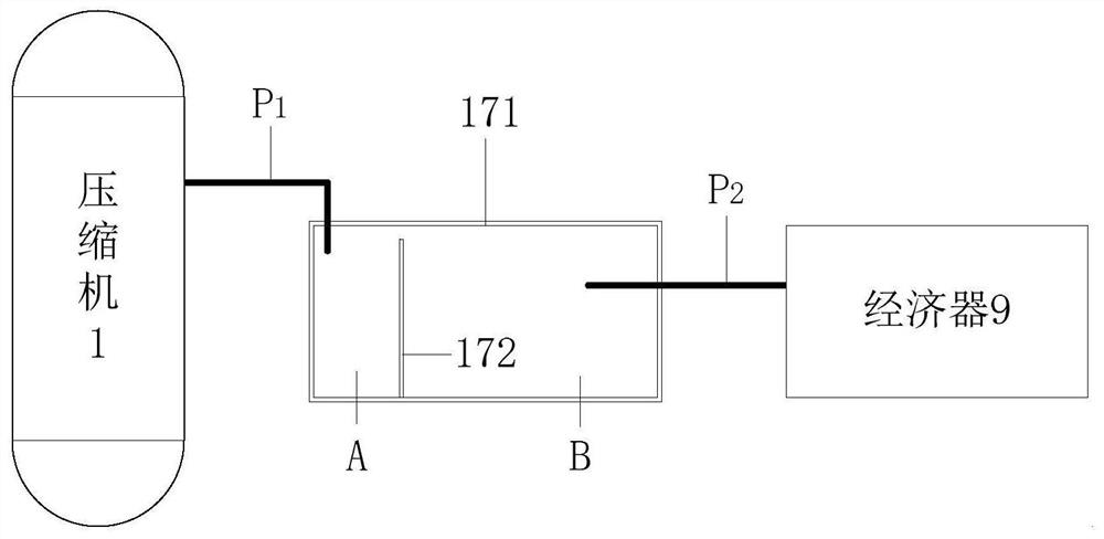
[0005] In order to solve the above-mentioned problems in the prior art, that is, the disturbance of the air supply pipeline and the vibration of the compressor caused by the fast flow rate of the refrigerant in the air supply pipeline, and the compression caused by the impact of the liquid return of the compressor on the scroll of the compressor To solve the problem of shortening the service life of the air conditioner, the present invention provides an air conditioner outdoor unit, which includes a compressor, an economizer, and an air supply pipeline connected between the compressor and the economizer. A pressure vessel on the air pipeline, the pressure vessel includes a vessel body and a refrigerant inlet and a refrigerant outlet arranged on the vessel body, the refrigerant inlet is connected to the auxiliary path outlet of the economizer, and the refrigerant outlet is connected to the compressor The air supply enthalpy interface of the machine is connected; the container body forms at least one cavity with a diameter larger than the diameter of the air supply pipeline in order to reduce the flow rate of the refrigerant, and the pressure vessel has a gas-liquid separation function to allow the refrigerant to The refrigerant flowing out of the outlet is a gaseous refrigerant

Method used


Image

  • Air conditioner outdoor unit and air conditioner
  • Air conditioner outdoor unit and air conditioner
  • Air conditioner outdoor unit and air conditioner

Examples


Embodiment Construction

[0029] Preferred embodiments of the present invention are described below with reference to the accompanying drawings. Those skilled in the art should understand that these embodiments are only used to explain the technical principles of the present invention, and are not intended to limit the protection scope of the present invention.

[0030] It should be noted that, in the description of the present invention, the terms "center", "upper", "lower", "left", "right", "vertical", "horizontal", "inner", "outer" etc. The terms of the indicated direction or positional relationship are based on the direction or positional relationship shown in the drawings, which are only for the convenience of description, and do not indicate or imply that the device or element must have a specific orientation, be constructed and operated in a specific orientation , and therefore cannot be construed as a limitation of the present invention. In addition, the terms "first", "second", and "third" ar...


PUM


Abstract

The invention relates to the field of air conditioners, in particular to an air conditioner outdoor unit and an air conditioner. The invention aims to solve the problem of disturbance of the gas supply pipeline caused by the high flow velocity of the refrigerant in the gas supply pipeline and the problem of shortened service life caused by the liquid return of the compressor. For this purpose, the outdoor unit of the present invention includes a pressure container arranged on the gas supply pipeline, the pressure vessel includes a container body, the container body forms at least one cavity with a diameter larger than that of the gas supply pipeline to reduce the flow rate of the refrigerant, and the pressure vessel has a gas The liquid separation function makes the refrigerant flowing out of the refrigerant outlet a gaseous refrigerant. The invention reduces the flow velocity of the refrigerant in the gas supply pipeline through the pressure vessel and allows the refrigerant to enter the compressor in gaseous form through the gas supply enthalpy increasing interface, which can reduce the vibration of the gas supply pipeline and avoid liquid return of the compressor to increase the life of the compressor.

Description

technical field [0001] The invention relates to the technical field of air conditioners, in particular to an outdoor air conditioner unit and an air conditioner. Background technique [0002] The compressor is the core device of the air conditioner, and it is usually installed on the outdoor unit of the air conditioner. The working performance of the compressor in the low temperature environment is limited. The characteristics of the air-supplementing and enthalpy-increasing compressor enable it to increase the exhaust volume of the system and reduce the exhaust temperature of the compressor in a low-temperature environment, which can ensure its high working performance under low-temperature conditions. In addition , The air-supplementing enthalpy-increasing compressor has the advantages of safety, reliability, energy saving and high efficiency. Therefore, the air-supplementing enthalpy-increasing compressor is widely used in air-conditioning products. [0003] The air supp...

Claims


Application Information

Patent Timeline
Patent Type & Authority Patents(China)
IPC IPC(8): F25B13/00F25B41/40F25B41/20F25B41/34F25B43/00F25B49/02
CPCF25B13/00F25B43/00F25B49/02F25B2313/02741F25B2500/13F25B2400/13F25B41/40F25B41/31F25B41/20
Inventor 李庆辉远义忠任善军毛守博
Owner QINGDAO HAIER AIR CONDITIONING ELECTRONICS CO LTD
Learn More