Optical fiber transmission device and method for total station calibration

A technology of total station and standard optical fiber, which is applied in the field of optical fiber transmission device for total station calibration, can solve the problems of harsh calibration environment, low measurement accuracy and high construction cost, achieve low-cost design, avoid complicated steps, Portable effect

Active Publication Date: 2019-04-16
THE 41ST INST OF CHINA ELECTRONICS TECH GRP
View PDF11 Cites 3 Cited by
  • Summary
  • Abstract
  • Description
  • Claims
  • Application Information

AI Technical Summary

Problems solved by technology

[0006] (1) Based on the "mirror + beamsplitter" technology, the collimation adjustment of the mirror and the beamsplitter is relatively complicated, and the optical path of the spatial optical path is not easy to control. At the same time, the operability is poor, and it is not easy to provide external measurement and calibration services.
[0007] (2) Based on the "spatial optical path target positioning" technology, it occupies a large

Method used


Image

  • Optical fiber transmission device and method for total station calibration

Examples


Embodiment 1

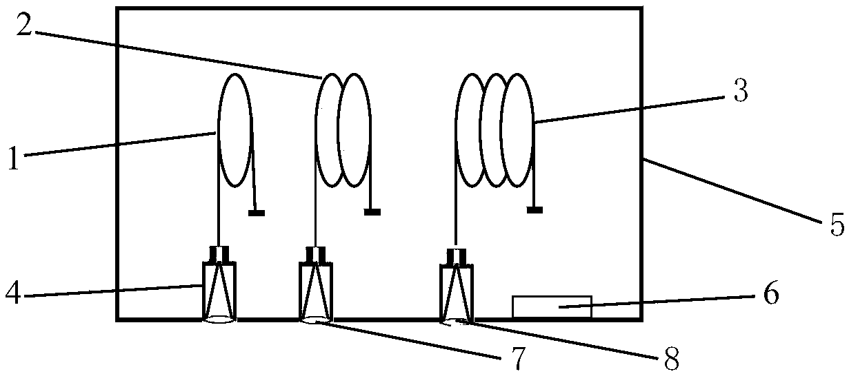
[0032] Such as figure 1 As shown, an optical fiber transfer device for calibration of a total station includes a chassis 5, and a temperature control and display system 6, a multimode optical fiber, a self-focusing collimating lens and an optical fiber jumper are placed inside the chassis 5; the multimode optical fiber The starting end of the self-focusing collimating lens is connected to one end of the self-focusing collimating lens, and the tail end is connected to the fiber jumper, and the connection part is coated with a high reflection film, and the other end of the self-focusing collimating lens is connected to the total station.

[0033] The chassis 5 is configured to protect and package the multimode optical fiber, the self-focusing collimation lens, the optical fiber jumper and the temperature control and display system 6 in the chassis 5;

[0034] The temperature control and display system 6 is configured to control the temperature of the chassis 5 and display the co...

Embodiment 2

[0038] On the basis of above-mentioned embodiment 1, the present invention also mentions a kind of optical fiber transmission method that is used for total station calibration, specifically comprises the following steps:

[0039] Step 1: Turn on the total station and warm up for 30 minutes;

[0040] Step 2: Align the total station with the first self-focusing collimating lens corresponding to the first multimode standard fiber, and record the measured value of the first multimode standard fiber after the measurement of the total station is completed;

[0041] Step 3: Align the total station with the second self-focusing lens corresponding to the second multimode standard fiber, and record the measured value of the second multimode standard fiber after the measurement of the total station is completed;

[0042]Step 4: align the total station with the third self-focusing lens corresponding to the third multimode standard optical fiber, and record the measured value of the third ...


PUM


Abstract

The invention discloses an optical fiber transmission device and method for total station calibration, and belongs to the technical field of photoelectric ranging calibration. The device comprises a case; a temperature control and display system, a multi-mode optical fiber, a self-focusing collimating lens and an optical fiber jumper wire are arranged in the case; the starting end of the multi-mode optical fiber is connected with one end of the self-focusing collimating lens, and the tail end of the multi-mode optical fiber is connected with the optical fiber jumper wire; and the other end ofthe self-focusing collimating lens is connected with a total station. A traditional baseline field method is replaced with a standard optical fiber which is controllable in temperature and is subjected to special processing, so that a portable working mode that the total station calibration is not affected by the external environment is achieved; by changing a length value of the standard opticalfiber, the calibration of variable values of the total station under different measuring ranges are realized; and a standard optical fiber method is used to replace a method for simulating an opticaldistance through return of an optical path between plane mirrors, so that the complicated steps of optical path collimation adjustment are avoided, and the low-cost design of transmission standards isalso achieved.

Description

technical field [0001] The invention belongs to the technical field of photoelectric ranging calibration, and in particular relates to an optical fiber transmission device and method for calibrating a total station. Background technique [0002] At present, the commonly used calibration method of total station is mainly the field baseline field method. Because this method occupies too much space on the one hand, the operation is time-consuming and laborious; on the other hand, it is easily affected by the outdoor weather, the calibration verification efficiency is low, and the work quality cannot be improved. . The total station calibration methods are mainly based on "mirror + beam splitter", based on "spatial optical path target positioning", based on "GPS and automatic tracking measurement" and other schemes. Based on the "mirror + beam splitter" scheme, whether the position of the mirror is offset will directly affect the size of the optical path and the optical path, a...

Claims


Application Information

Patent Timeline
IPC IPC(8): G01C25/00G01C15/00
CPCG01C15/00G01C25/00
Inventor 郑祥亮孙权社陈坤峰王恒飞郑光金赵发财王少水韩忠
Owner THE 41ST INST OF CHINA ELECTRONICS TECH GRP
Why Eureka
Try Eureka