Supercharge Your Innovation With Domain-Expert AI Agents!

Magnetic gathering ring for current sensor

A technology of current sensor and magnetic gathering ring, which is applied in the direction of measuring current/voltage, parts of electrical measuring instruments, instruments, etc., can solve the problems of high cost and large size of magnetic gathering ring, and achieve low cost and small magnetic core loss , The effect of high saturation magnetic induction

Active Publication Date: 2021-05-18
NO 49 INST CHINESE ELECTRONICS SCI & TECH GRP
View PDF12 Cites 0 Cited by
  • Summary
  • Abstract
  • Description
  • Claims
  • Application Information

AI Technical Summary

Problems solved by technology

[0006] The present invention aims to solve the problem of large size and high cost of the magnetic gathering ring in the existing current sensor, and proposes a magnetic gathering ring for the current sensor

Method used


Image

  • Magnetic gathering ring for current sensor
  • Magnetic gathering ring for current sensor

Examples


specific Embodiment approach 1

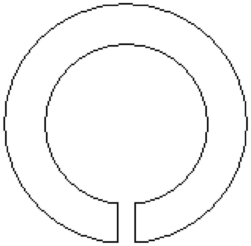
[0020] Specific implementation mode one: the following combination figure 1 and figure 2 This embodiment is described. The novel magnetic ring for the current sensor described in this embodiment includes four sets of annular magnetic rings with air gaps. The four circular magnetic rings have the same structure and size, and the circular magnetic rings It includes a main body of a magnetic ring made of single crystal silicon material and a layer of soft iron material, the layer of soft iron material is plated on the outside of the main body of a magnetic ring made of single crystal silicon material, and the width of the layer of soft iron material is smaller than that of the main body of a magnetic ring made of single crystal silicon material width;

[0021] The four circular magnetic rings are sequentially combined into an integrated structure from top to bottom through the bonding process; the air gap positions of the four circular magnetic rings in the integrated structure...

specific Embodiment approach 2

[0023] Specific implementation mode two: the following combination figure 2 Describe this embodiment mode, this embodiment mode is further described to a kind of current sensor described in Embodiment 1 and uses the magnetism gathering ring, and the air gap of the ring-shaped magnetic ring is the rectangular opening opened on the side wall of the ring-shaped magnetic ring, The length of the rectangular opening runs through the upper and lower ends of the annular magnetic ring.

specific Embodiment approach 3

[0024] Specific embodiment three: This embodiment further explains the magnetic ring for a current sensor described in embodiment one or two, the width of the soft iron material layer is greater than 1 / 2 of the width of the main body of the single crystal silicon material magnetic ring .


PUM

PropertyMeasurementUnit
thicknessaaaaaaaaaa
thicknessaaaaaaaaaa

Abstract

A magnetic gathering ring for a current sensor belongs to the technical field of current sensors. The invention solves the problems of large size and high cost of the magnetic gathering ring in the existing current sensor. The present invention includes four groups of annular magnetic rings with air gaps, the four circular magnetic rings have the same structure and size, and the circular magnetic rings include a single crystal silicon material magnetic ring body and a soft iron material layer. The soft iron material layer is plated on the outside of the main body of the monocrystalline silicon material magnetic ring, and the width of the soft iron material layer is smaller than the width of the main body of the single crystal silicon material magnetic ring; the four circular magnetic rings are bonded from top to bottom through the bonding process are sequentially combined into an integral structure; the positions of the air gaps of the four circular magnetic rings in the integral structure are all corresponding. The invention is suitable for use as a magnetic gathering ring of a current sensor.

Description

technical field [0001] The invention belongs to the technical field of current sensors. Background technique [0002] In recent years, with the continuous improvement of people's requirements for the working stability of electric motors for new energy vehicles, solar and wind power inverters, current sensors are widely used in new energy, intelligent transportation, industrial control, smart home appliances and smart grids, etc. Field measurements. The non-contact current sensor is mainly used for the measurement of large current. The working principle of this type of current sensor is: the magnetic field generated by the primary current is collected by the magnetic field gathering ring, and the Hall element placed in the magnetic field gathering ring collects the magnetic field. , to generate a Hall voltage proportional to the primary side magnetic field, and by measuring the size of the Hall voltage, the isolated detection of the primary side current can be realized. [...

Claims


Application Information

Patent Timeline
Patent Type & Authority Patents(China)
IPC IPC(8): G01R1/02G01R19/00
CPCG01R1/02G01R19/00
Inventor 宋尔冬毕佳宇王辉张松孙立凯
Owner NO 49 INST CHINESE ELECTRONICS SCI & TECH GRP
Features
  • R&D
  • Intellectual Property
  • Life Sciences
  • Materials
  • Tech Scout
  • Unparalleled Data Quality
  • Higher Quality Content
  • 60% Fewer Hallucinations
Learn More