Laser pulse distance measuring method for correcting measurement error by utilizing received signal width

A technology for receiving signals and laser pulses, applied in measurement devices, using re-radiation, radio wave measurement systems, etc., can solve problems such as the inability to achieve long-distance measurement, and achieve low cost, low cost, and simple implementation.

Inactive Publication Date: 2019-04-16
SHANGHAI RADIO EQUIP RES INST
View PDF3 Cites 19 Cited by
  • Summary
  • Abstract
  • Description
  • Claims
  • Application Information

AI Technical Summary

Problems solved by technology

Although the phase method has high accura...

Method used


Image

  • Laser pulse distance measuring method for correcting measurement error by utilizing received signal width
  • Laser pulse distance measuring method for correcting measurement error by utilizing received signal width
  • Laser pulse distance measuring method for correcting measurement error by utilizing received signal width

Examples


Embodiment Construction

[0039] The present invention provides a laser pulse ranging method that uses the received signal width to correct measurement errors. In order to make the present invention more obvious and understandable, the present invention will be further described below in conjunction with the accompanying drawings and specific embodiments.

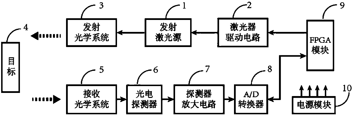
[0040] In this implementation, an FPGA-based pulse laser ranging prototype is built, such as figure 1 As shown, the pulsed laser ranging prototype includes: emitting laser light source 1, laser drive circuit 2, emitting optical system 3, receiving optical system 5, photodetector 6, detector amplifier circuit 7, A / D converter (analog to digital Converter) 8 and FPGA module 9.

[0041] The emitting laser source 1 is driven by the laser driving circuit 2 to emit light. The outgoing light is shaped by the emitting optical system 3 and exits with a certain beam divergence angle, and then irradiates the measured target 4. The return light signal reflect...


PUM


Abstract

The invention discloses a laser pulse distance measuring method for correcting a measurement error by utilizing received signal width. The method comprises the following steps that a pulse laser is adopted for a light source, a driving circuit drives the laser to emit narrow-pulse-width laser pulses, and the laser pulses are emitted at a certain beam-divergence angle after being shaped by a transmitting optical system. Target echo signals are converged on the photosensitive surface of a photoelectric detector through a receiving optical system to achieve photoelectric conversion. Electric signals are converted into digital signals after being preprocessed. An FPGA phase-shifting clock is used for carrying out high-speed sampling on echoes, and the time delay and the receiving signal widthof the reflected echoes are measured. A data table is made according to the relation curve of actually measured received signal width and the delay compensation amount. A distance measuring machine isused for obtaining time identification errors so as to correct a distance measuring result through a table look-up mode according to the leading edge time and the received signal width measured by the FPGA. According to the invention, higher distance measuring precision can be realized, and the method has a good application prospect in the relevant field of laser distance measuring.

Description

technical field [0001] The invention relates to the technical field of laser radar, in particular to a laser pulse ranging method for correcting measurement errors by using the received signal width. Background technique [0002] At present, laser ranging methods are mainly phase method and pulse method. Although the phase method has high precision in ranging, it cannot realize long-distance measurement. The pulse method has the advantages of long detection distance and low coherence requirements for light sources. It uses the characteristics of extremely short laser pulse duration, relatively concentrated energy in time, and large instantaneous power. Under the same average optical power , enabling long-distance measurements with limited precision. Therefore, it is widely used in the fields of construction engineering, industry, aerospace, military, atmospheric detection and robotics. Different application fields have different requirements for measurement range and accu...

Claims


Application Information

Patent Timeline
IPC IPC(8): G01S17/10G01S7/486G01S7/497
CPCG01S7/486G01S7/497G01S17/10
Inventor 王永志杨德钊张明祎都金丹王艳平戴雯
Owner SHANGHAI RADIO EQUIP RES INST
Why Eureka
Try Eureka