Multi-switch synchronous isolation driving circuit with over-current protection
A technology for isolating drive circuits and overcurrent protection, which is applied to emergency protection circuit devices, emergency protection circuit devices, and circuit devices for limiting overcurrent/overvoltage, and can solve the problem of reducing short-circuit withstand time and reducing IGBT impedance , short-circuit current increase and other problems, to achieve the effect of increasing the voltage amplitude, increasing the turn-off speed, and improving the ability of electromagnetic compatibility
- Summary
- Abstract
- Description
- Claims
- Application Information
AI Technical Summary
Problems solved by technology
Method used
Image
Examples
Embodiment 1
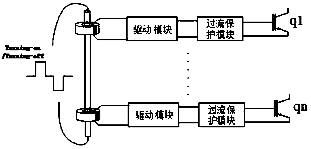
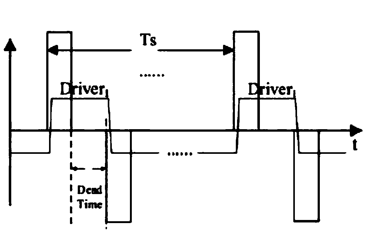
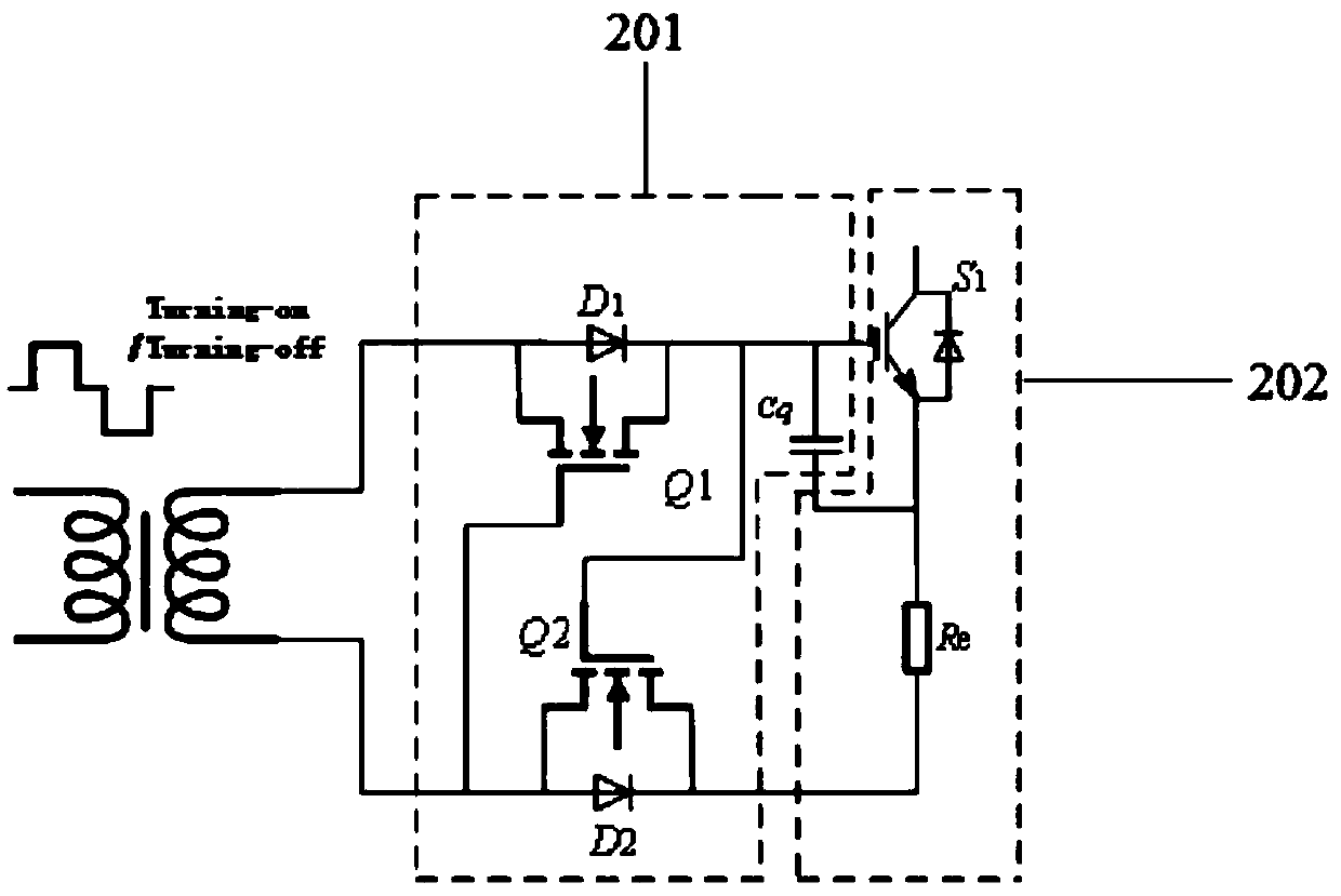
[0022] Such as figure 1 and figure 2 As shown, a multi-switch synchronous isolation drive circuit with overcurrent protection in this embodiment is used to synchronously drive a plurality of semiconductor switch tubes, including: a control circuit (not shown in the figure), a primary side drive circuit (in the figure not shown), the magnetic isolation transformer 10 and the secondary drive control circuit 20.
[0023] A control circuit for generating and outputting analog signals.
[0024] The primary side drive circuit is electrically connected with the control circuit and used for converting the analog signal into a bipolar pulse signal.
[0025] The primary side drive circuit is used to generate a bipolar pulse signal with adjustable pulse width, phase and frequency.
[0026] The magnetic isolation transformer 10 has a primary winding electrically connected to the primary driving circuit, a plurality of core-through magnetic rings connected in series with the primary wi...
Embodiment 2
[0038] This embodiment has a control circuit (not shown in the figure), a primary side drive circuit (not shown in the figure), a magnetic isolation transformer 10 and a secondary side drive control circuit. Compared with Embodiment 1, the overcurrent protection module 203 of this embodiment is different, and has the following structure:
[0039] Such as Figure 4 As shown, the overcurrent protection module 203 includes a semiconductor switch S1 whose gate is connected to one end of the energy storage capacitor Cq and whose emitter is connected to the other end of the energy storage capacitor Cq. One end is connected to the emitter of the semiconductor switch S1 and the other end is connected to the second end of the semiconductor switch S1. The drains of the two MOS transistors Q2 are connected to the sampling resistor Re and the bidirectional voltage regulator transistors Z1 and Z2 connected in parallel to the gate of the semiconductor switch S1 and the drain of the second M...
PUM
 Abstract
Description
Claims
Application Information
 - R&D
- Intellectual Property
- Life Sciences
- Materials
- Tech Scout
- Unparalleled Data Quality
- Higher Quality Content
- 60% Fewer Hallucinations
Browse by: Latest US Patents, China's latest patents, Technical Efficacy Thesaurus, Application Domain, Technology Topic, Popular Technical Reports.
© 2025 PatSnap. All rights reserved.Legal|Privacy policy|Modern Slavery Act Transparency Statement|Sitemap|About US| Contact US: help@patsnap.com


