An implantable fully bioabsorbable vascular polymer scaffold

A polymer, implantable technology

Active Publication Date: 2021-03-26
SHENZHEN SALUBRIS BIOMEDICAL ENG CO LTD
View PDF17 Cites 0 Cited by
  • Summary
  • Abstract
  • Description
  • Claims
  • Application Information

AI Technical Summary

Problems solved by technology

However, this solution also has relatively large deficiencies in setting smaller crimping diameters, and especially in the support and stability of its sections when used in polymer stents
[0012] In addition, the tube wall thickness of the existing degradable stent is affected by the material and processing methods, which are thicker than the metal stent, which is 2 times or more than the metal stent, which incre...

Method used


Image

  • An implantable fully bioabsorbable vascular polymer scaffold
  • An implantable fully bioabsorbable vascular polymer scaffold
  • An implantable fully bioabsorbable vascular polymer scaffold

Examples


Embodiment 1

[0058] Embodiment 1 An implantable fully bioabsorbable vascular polymer stent

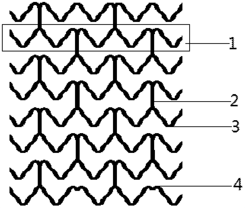
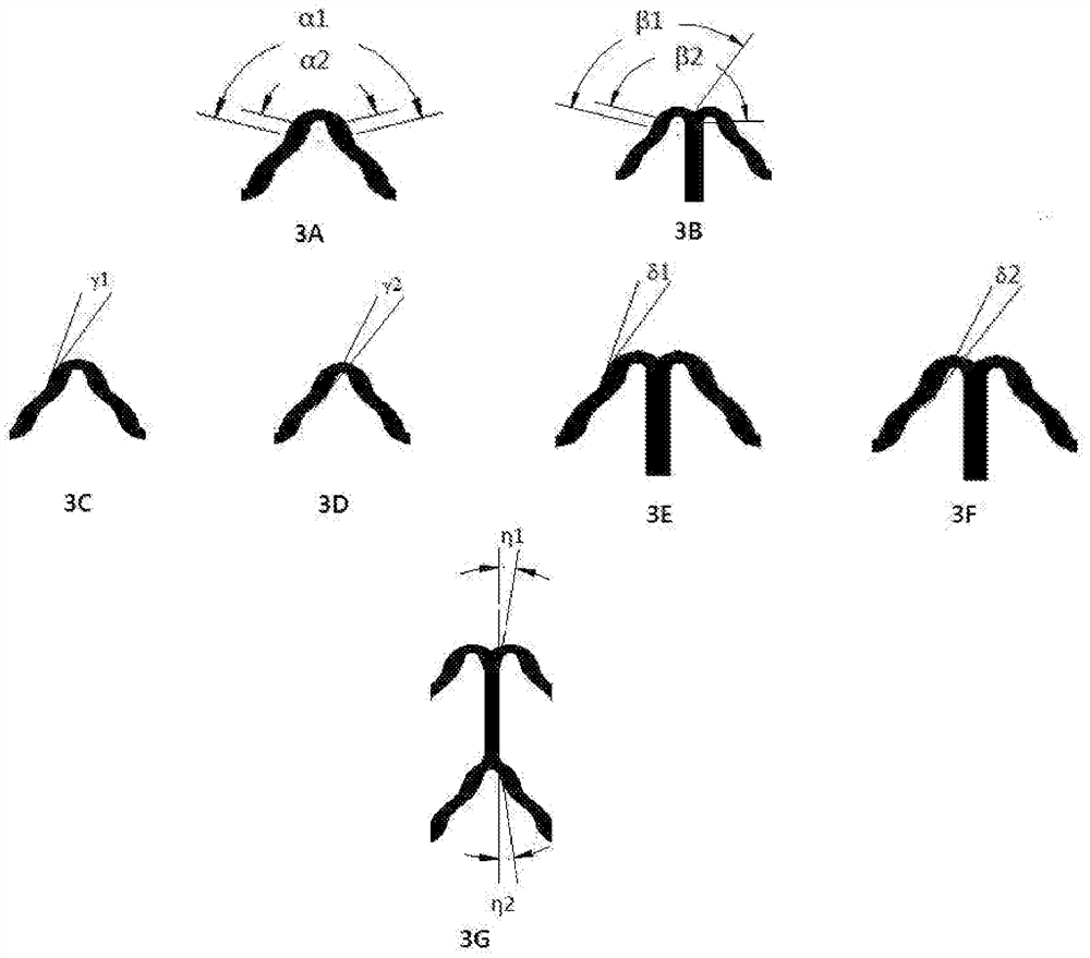
[0059] See attached figure 1 , 2 As shown in 3A-3G, an implantable fully bioabsorbable vascular polymer stent, made of polylactic acid, includes more than five ring-shaped corrugated support rods 1, and connecting rods 2 connected to the support rod 1 at intervals, The support rod 1 of the bracket is formed by alternately connecting "Ω"-shaped waves 3 and "m"-shaped waves 4, and the connection between two adjacent support rods is formed by connecting rods 2 in the "Ω"-shaped wave The top is connected with the "m"-like wave bottom.

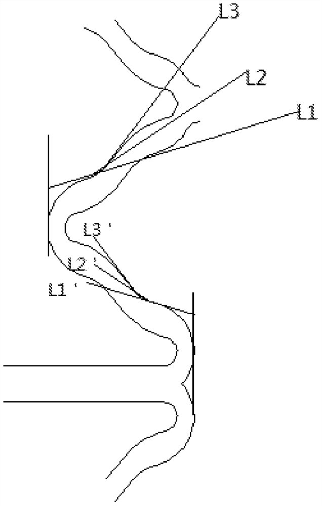
[0060] The class "m" shaped wave 4, such as image 3 As shown in A, and "Ω" shaped wave 3, such as image 3 As shown in B, it is composed of two groups of positive "s" and inverted "s" connections, respectively as figure 2 shown.

[0061] The connecting rods between the two adjacent supporting rods are all straight rods.

[0062] This implantable fully bioabsorb...

Embodiment 2

[0063] Embodiment 2 An implantable fully bioabsorbable vascular polymer stent

[0064] See attached figure 1 , 2As shown in 3A-3G, an implantable fully bioabsorbable vascular polymer stent includes five or more ring-shaped corrugated support rods 1, and connecting rods 2 connected to the support rod 1 at intervals, and the embodiment 1 The difference is that in this specific embodiment, the widths of the support rods and the connecting rods are different, the width of the support rods at both ends of the bracket is the thickest, and the width of the connecting rods at the two ends of the bracket is next, Then to the width of the remaining support rods, the width of the remaining connecting rods is the thinnest. Among them, the angle between the positive "s" and inverted "s" connecting segments is 5-10 degrees.

Embodiment 3

[0065] Example 3 An implantable fully bioabsorbable vascular polymer stent

[0066] See attached figure 1 , 2 As shown in 3A-3G, an implantable fully bioabsorbable vascular polymer stent includes five or more ring-shaped corrugated support rods 1, and connecting rods 2 connected to the support rod 1 at intervals, and the embodiment 1 The difference is that in this specific embodiment, the widths of the support rods and the connecting rods are different, the width of the support rods at both ends of the bracket is the thickest, and the width of the connecting rods at the two ends of the bracket is next, Then to the width of the remaining support rods, the width of the remaining connecting rods is the thinnest. Among them, the angle between the positive "s" and inverted "s" connecting segments is 40-45 degrees.


PUM

PropertyMeasurementUnit
Angleaaaaaaaaaa
Angleaaaaaaaaaa
Angleaaaaaaaaaa

Abstract

Disclosed is an implant-type, completely bioabsorbable, vascular polymer stent comprising five or more annular corrugated support struts (1), and connecting struts (2) spaced apart and connected between the support struts (1). The support struts (1) are formed by corrugations resembling an "Ω" shape (3) and corrugations resembling an "m" shape (4) being alternately connected with each other, wherein the corrugations resembling an "Ω" shape (3) and the corrugations resembling an "m" shape (4) are respectively composed of two sets of upright "s" parts and inverted "s" parts connected together, and the connection between two adjacent support struts (1) is formed by means of the connecting struts (2) connecting the top of the corrugations resembling an "Ω" shape (3) and the bottom of the corrugations resembling an "m" shape (4). The stent balances radial supporting force, wall thickness and flexibility, has good passing-through performance, can also provide sufficient mechanical support at a lesion segment for a specified period of time for wound healing, and is be gradually absorbed by the body after the wound heals, with good endothelialisation, thereby effectively reducing the stent restenosis rate and the risk of late stent thrombosis.

Description

technical field [0001] The invention belongs to the field of medical devices, in particular to an implantable fully bioabsorbable blood vessel polymer stent. Background technique [0002] Since the first metal stent Palmaz-Schatz was implanted into the human body in 1985, stent interventional therapy has successfully solved the problem of high restenosis rate in the era of simple balloon dilatation, and has become the main method of clinical treatment. After the metal stent is implanted in the human body, it is found that the restenosis rate in the stent is still as high as about 20% due to inflammatory reactions, neointimal hyperplasia, negative vascular remodeling, and delayed endothelialization of the stent. [0003] In order to solve this problem, the first generation of polymer-coated drug-eluting stents came into being. The emergence of drug-eluting stents will reduce the restenosis after interventional treatment from 30-40% in the era of simple PTCA to 15-25% in the ...

Claims


Application Information

Patent Timeline
IPC IPC(8): A61F2/07A61F2/915A61F2/89
CPCA61F2/07A61F2/89A61F2/915
Inventor 陈泳胡晓露高康荣申峰
Owner SHENZHEN SALUBRIS BIOMEDICAL ENG CO LTD
Why Eureka
Try Eureka