High-temperature and high-pressure micro tube and shell type heat exchanger

A high temperature and high pressure, heat exchanger technology, applied in the field of heat exchange, can solve the problems of unsuitable metal micro-tube sealing connection, inability to meet high temperature and high pressure, increase processing difficulty, etc., achieve compact structure, good pressure bearing capacity, and reduce processing difficulty. and cost effects

Active Publication Date: 2019-04-19
颍上县祥盛建设管理有限公司
View PDF9 Cites 3 Cited by
  • Summary
  • Abstract
  • Description
  • Claims
  • Application Information

AI Technical Summary

Problems solved by technology

In this patent, the double-sealed connection of tube bundles, headers, and horizontal partitions can improve the sealing performance of the heat exchanger, but it also increases the processing steps and increases the difficulty of processing, and the expansion joint is not suitable for metal microtubes under high temperature and high pressure. sealed connection
[0008] Chinese patent, Patent Publication No. CN 103128519A discloses a method and device for manufacturing a microchannel heat exchanger. The heat exchanger tube bundle and the header of the heat exchanger are connected by cold extrusion, which saves raw materials, Energy, the advantages of improving efficiency and reducing costs, but this process is not suitable for high temperature and high pressure working conditions
However, the threaded connection between the heat exchanger tube bundle and the tube sheet cannot meet the conditions of high temperature and high pressure.

Method used


Image

  • High-temperature and high-pressure micro tube and shell type heat exchanger
  • High-temperature and high-pressure micro tube and shell type heat exchanger
  • High-temperature and high-pressure micro tube and shell type heat exchanger

Examples


Embodiment Construction

[0049] In order to make the purpose of the invention, technical solution and beneficial technical effects of the present invention clearer, the present invention will be further described in detail below in conjunction with the accompanying drawings and specific implementation methods. It should be understood that the specific implementations described in this specification are only for explaining the present invention, not for limiting the present invention.

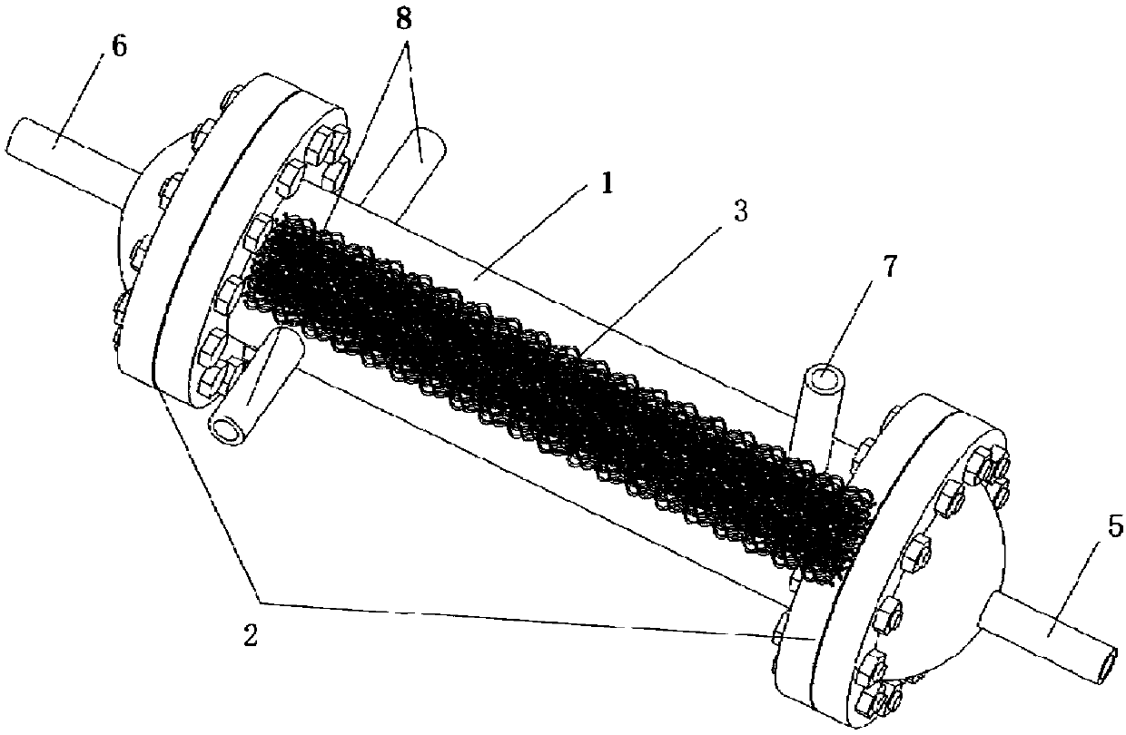
[0050] In this embodiment, the present invention provides a high temperature and high pressure micro shell and tube heat exchanger, such as figure 1 As shown in: It consists of heat exchanger shell 1, tube box 2, heat exchanger tube bundle 3 and tube sheet sealing device; tube box 2 is installed at both ends of heat exchanger shell 1; among them, one tube box 2 A cold fluid inlet 5 is provided, and a cold fluid outlet 6 is provided on the other pipe box 2, and the heat exchanger shell 1 is provided with a hot fluid inle...


PUM


Abstract

The invention relates to a high-temperature and high-pressure micro tube and shell type heat exchanger. The heat exchanger is simple and compact in structure, internal flow and temperature distribution is uniform, the heat exchange efficiency is high, the sealing performance is good, and resistance to high temperature and high pressure is achieved. The heat exchanger structurally comprises a heatexchanger shell, tube boxes and heat exchanger tube bundles. The tube boxes are mounted at the two ends of the heat exchanger shell. A cold fluid inlet is formed in one tube box, a cold fluid outlet is formed in the other tube box, and a hot fluid inlet and a hot fluid outlet are formed in the heat exchanger shell. The multiple heat exchanger tube bundles are axially distributed in the heat exchanger shell, and a tube plate sealing device is arranged in each tube box. The two ends of the multiple heat exchanger tube bundles are inserted into the tube plate sealing devices and sealed by the tube plate sealing devices, one end of each heat exchanger tube bundle communicates with the cold fluid inlet, and the other end of each heat exchanger tube bundle communicates with the cold fluid outlet. Each heat exchanger tube bundle is a sinusoidal bent tube or a trapezoidal bent tube.

Description

technical field [0001] The invention belongs to the field of heat exchange, and in particular relates to a high-temperature, high-pressure micro shell-and-tube heat exchanger. Background technique [0002] In the research and development of the fourth-generation high-temperature gas-cooled reactor nuclear power plant, the supercritical carbon dioxide Brayton cycle is considered to be a new, efficient and safe energy cycle system. In the supercritical carbon dioxide Brayton cycle, the regenerator is one of the most important heat exchange components, and its thermal hydraulic performance has an important impact on the efficiency of the entire cycle and the size of the system. [0003] At present, the heat exchangers used in the second and third generation pressurized water reactor nuclear power plants are generally shell and tube heat exchangers. The traditional shell-and-tube heat exchanger has the advantages of simple structure, low cost, wide cross section and easy cleani...

Claims


Application Information

Patent Timeline
Patent Type & Authority Applications(China)
IPC IPC(8): F28D7/08F28F9/04F28F9/00
CPCF28D7/082F28F9/00F28F9/04
Inventor 王青青许博黄鑫阴勇光王海军
Owner 颍上县祥盛建设管理有限公司
Why Eureka
Try Eureka