Method for measuring surface shape of optical interface

An optical interface and surface type technology, which is applied to measurement devices, optical devices, instruments, etc., can solve the problems of optical element pollution, high cost, and difficult wavefront recovery, and achieve a simple and reliable system, low cost, and fast detection rate. Effect

Inactive Publication Date: 2019-04-19
SICHUAN UNIV
View PDF8 Cites 2 Cited by
  • Summary
  • Abstract
  • Description
  • Claims
  • Application Information

AI Technical Summary

Problems solved by technology

Due to the existence of multiple optical interfaces, the light waves reflected by each optical interface will interfere with the reference surface light waves, so the interference fringes on the fringe acquisition system are composed of interference fringes of multiple interfaces, which brings great difficulties to the wave front restoration , using the traditional phase shift algorithm will produce a large error
In response to this situation, the common method is to coat the rear surface of the component with a refractive index matching substance such as Vaseline or matting paint to eliminate reflected light, but it will pollute the optical component and cannot eliminate the reflection of the optical interface inside the optical component
If the wavelength-tuned phase-shift method or the wavelength-tuned time-domain Fourier transform method is used, multiple interference fringes need to be collected, and the algorithm is complex, which has the disadvantages of low detection speed and high cost

Method used


Image

  • Method for measuring surface shape of optical interface
  • Method for measuring surface shape of optical interface
  • Method for measuring surface shape of optical interface

Examples


Embodiment 1

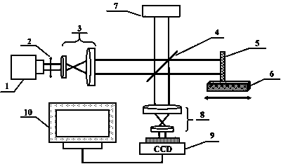
[0049] The CoherentLegend laser that ultrashort pulse laser 1 adopts in the present embodiment, central wavelength 800nm, pulse width 60 fs , the repetition frequency is adjustable from 1 to 1000Hz, and the single pulse capacity is 1.5 mJ; the filter 2 adopts the FB800-10 filter of Thorlabs; the optical matching system 3 adopts a telescope system with a magnification of 10 times; the beam splitter 4 adopts Daheng Optoelectronics Co., Ltd.’s GCC-4111 series ordinary broadband spectroscopic flat film, the ratio of transmittance to reflectance is 3:7; the reference mirror 5 is a customized precision optical flat mirror with a diameter of 50.8 mm and a surface flatness of λ / 20. The reflectivity at 700-900 nm is greater than 99%; the electronically controlled mobile translation stage 6 is the GCD-101050M small electronically controlled displacement stage of Daheng Optoelectronics Company; Quartz plane mirror; the optical matching system 8 adopts a telescope system with a magnific...


PUM


Abstract

The invention relates to a method for measuring an interface surface shape of a multi-interface target body by adopting ultrashort pulse laser, which comprises the following steps of: selecting an ultrashort pulse laser light source; dividing the ultrashort laser pulse into two beams of light by a spectroscope after the ultrashort laser pulse is subjected to spectral filtering and enters a Michelson interferometer, and one beam of light is reflected by a reference mirror and enters an interference light receiving system as reference light; the other beam is reflected by the interface to be measured of the target body and enters the interference light receiving system as signal light; adjusting the length of the reference arm or the length of the measuring arm of the Michelson interferometer so that the reference light only interferes with the signal light reflected by the interface to be measured of the target body and does not interfere with the signal light reflected by other interfaces of the target body, and the computer system obtains the surface shape of the interface to be detected according to the acquired double-interface interference fringes. The method achieves the interface surface type measurement of the multi-interface target body by utilizing the coherence characteristic between the ultrashort pulses, which is a novel measurement method and has the advantages ofsimplicity, stability, high efficiency and the like.

Description

technical field [0001] The invention belongs to the field of surface shape measurement, and in particular relates to a method for measuring the surface shape of an optical interface. Background technique [0002] In recent decades, optical technology has been greatly developed, playing an increasingly important role in industrial applications and national economy. In the field of optics, the multi-interface optical element is a main optical element, and the surface shape of each interface has an important influence on the phase of the light field transmission. Therefore, the measurement of the surface shape of multi-interface optical components is becoming more and more important. [0003] In the surface measurement of multi-interface optical components, interferometry is often used. Due to the existence of multiple optical interfaces, the light waves reflected by each optical interface will interfere with the reference surface light waves, so the interference fringes on t...

Claims


Application Information

Patent Timeline
Patent Type & Authority Applications(China)
IPC IPC(8): G01B11/24
CPCG01B11/2441
Inventor 杨火木李洪儒邓国亮
Owner SICHUAN UNIV
Why Eureka
Try Eureka