
Satellite-borne DC-DC converter combiner output circuit with low transmission power consumption

A technology of a DC converter and an output circuit, which is applied in the conversion devices and instruments for converting DC power input into DC power output and output power, etc., can solve the problems of difficulty in diode heat dissipation design, failure of equipment to work normally, and reduction of power transmission efficiency. , to achieve the effect of improving design safety margin, improving power transmission efficiency, and simple and reliable circuit

Inactive Publication Date: 2019-04-19
AEROSPACE DONGFANGHONG DEV LTD
View PDF5 Cites 3 Cited by
  • Summary
  • Abstract
  • Description
  • Claims
  • Application Information

AI Technical Summary

Problems solved by technology

This design ensures the reliability of the secondary power supply, but due to the inherent characteristics of the diode, the voltage drop of the diode will vary greatly under different current and temperature conditions, resulting in a large voltage at the input terminal of the power supply of the electrical equipment. Fluctuation within the range, and the two DC-DC converters have alternate output, which may cause the equipment to fail to work properly in the occasion where the electrical equipment has a high requirement for the voltage fluctuation range
[0004] In addition, when the load current is large, the power consumed on the diode is large, which reduces the power transmission efficiency and brings difficulties to the heat dissipation design of the diode.

Method used


Image

  • Satellite-borne DC-DC converter combiner output circuit with low transmission power consumption
  • Satellite-borne DC-DC converter combiner output circuit with low transmission power consumption

Examples


Embodiment Construction

[0016] The present invention will be further described below in conjunction with the accompanying drawings and specific embodiments.

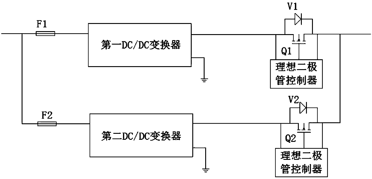
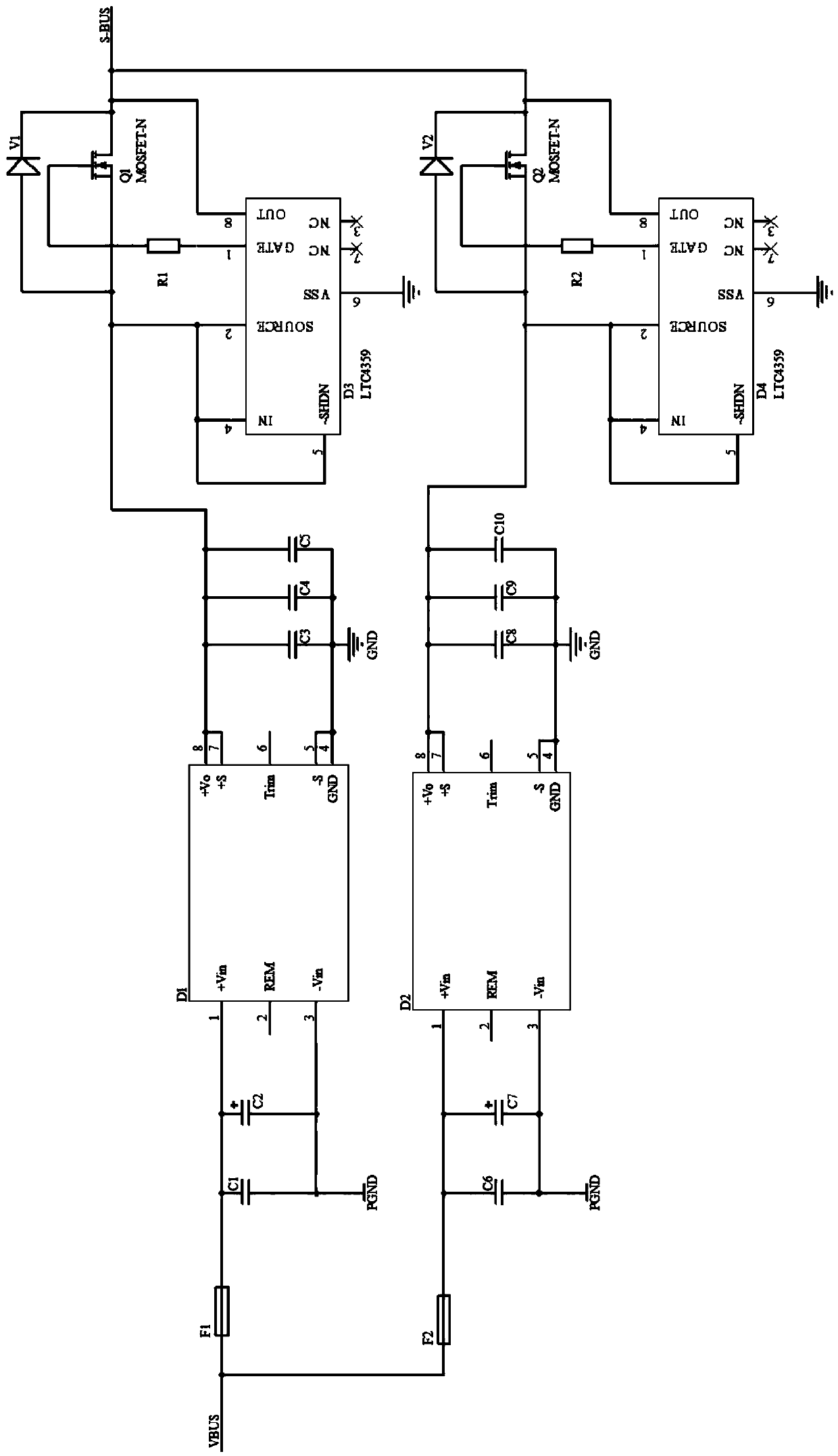
[0017] Such as figure 1 As shown, the combined output circuit of the on-board DC-DC converter with low transmission power consumption of the present invention includes a first DC-DC converter, a second DC-DC converter, a first fuse, and a second fuse , a first NMOS transistor, a second NMOS transistor, a first Schottky diode, a second Schottky diode, a first ideal diode controller and a second ideal diode controller. Wherein, the DC-DC converter has a remote compensation function; the input terminal of the positive line of the primary power supply passes through the first fuse, the second fuse and the first DC-DC converter and the second DC-DC converter respectively. The input terminal is connected; the output terminal of the DC-DC converter is connected to the source of the NMOS tube, the anode of the Schottky diode is connected to the source...


PUM


Abstract

The invention provides a satellite-borne DC-DC converter combiner output circuit with low transmission power consumption. The satellite-borne DC-DC converter combiner output circuit includes a first DC-DC converter D1, a second DC-DC converter D1, a first NMOS transistor Q1, a second NMOS transistor Q2, a first Schottky diode V1, a second Schottky diode V2, a first ideal diode controller D3 and asecond ideal diode controller D4, wherein a primary power supply main line input terminal is connected to primary power supply input terminals of D1 and D2; the output terminal of the DC-DC converteris connected to the source electrodes of the NMOS transistors, and the positive poles of the Schottky diodes are connected to the source electrodes of the NMOS transistors; the negative electrodes ofthe Schottky diodes are connected to the drain electrodes of the NMOS transistors; the control terminals of the ideal diode controllers are connected to the gate electrodes of the NMOS transistors; the ideal diode controllers detect the voltage drop between the source electrodes and the drain electrodes of the NMOS transistors to adjust the magnitude of the output current of power supply; and thesource electrodes of Q1 and Q2 are shorted together as an output terminal.

Description

technical field [0001] The invention relates to the technical field of spacecraft secondary power conversion, in particular to an on-board DC-DC converter combiner output circuit. Background technique [0002] The DC-DC converter converts the on-board primary power supply into the secondary power supply voltage required by the electrical equipment. In order to ensure the reliability of the power supply, two DC-DC converters are generally designed in parallel. Under normal conditions, the other can still supply power and output normally, ensuring the normal operation of the equipment on the star. [0003] Isolated DC-DC converters are widely used in spacecraft equipment, and dual-channel hot-standby DC-DC converters are often used to supply power to loads. In the design, a diode is connected in series at the output end of each DC-DC converter, and the cathodes of the two diodes are shorted together, and then output to electrical equipment. This design ensures the reliabilit...

Claims


Application Information

Patent Timeline
Patent Type & Authority Applications(China)
IPC IPC(8): H02M3/155
CPCH02M3/155H02M1/0048Y02B70/10
Inventor 吕红强赵溪林张龙龙梁晓华张浩翔王妍郭泉良
Owner AEROSPACE DONGFANGHONG DEV LTD
Learn More