Feeding device for pipe end forming machine

A feeding device and forming machine technology, which is applied in the direction of conveyors, conveyor objects, transportation and packaging, etc., can solve the problems of high labor intensity, low work efficiency, and large space occupation for workers

Pending Publication Date: 2019-04-23
张家港市润泰机械有限公司
View PDF0 Cites 2 Cited by
  • Summary
  • Abstract
  • Description
  • Claims
  • Application Information

AI Technical Summary

Problems solved by technology

[0003] 1. The pipe is manually transferred to the end processing station. The labor intensity of the workers is high and the work efficiency is low; or, it is transferred to the end processing station through the pipe transfer mechanism. At present, the drive of the pipe transfer mechanism is a chain drive, and the transmission accuracy Low, which is not conducive to the transfer of pipes between various processes, and takes up a lot of space;
[0004] 2. The pipe needs to be moved multiple times (including the movement to the end processing station and the movement to the inspection station after the end of the pipe is processed), and the connection between the end processing and the inspection process of the pipe is poor, which prolongs the cycle of the entire workflow , thus greatly affecting work efficiency;
[0005] 3. It requires a large number of staff and high labor costs

Method used


Image

  • Feeding device for pipe end forming machine
  • Feeding device for pipe end forming machine
  • Feeding device for pipe end forming machine

Examples


Embodiment Construction

[0045] The present invention will be further described in detail below through specific embodiments.

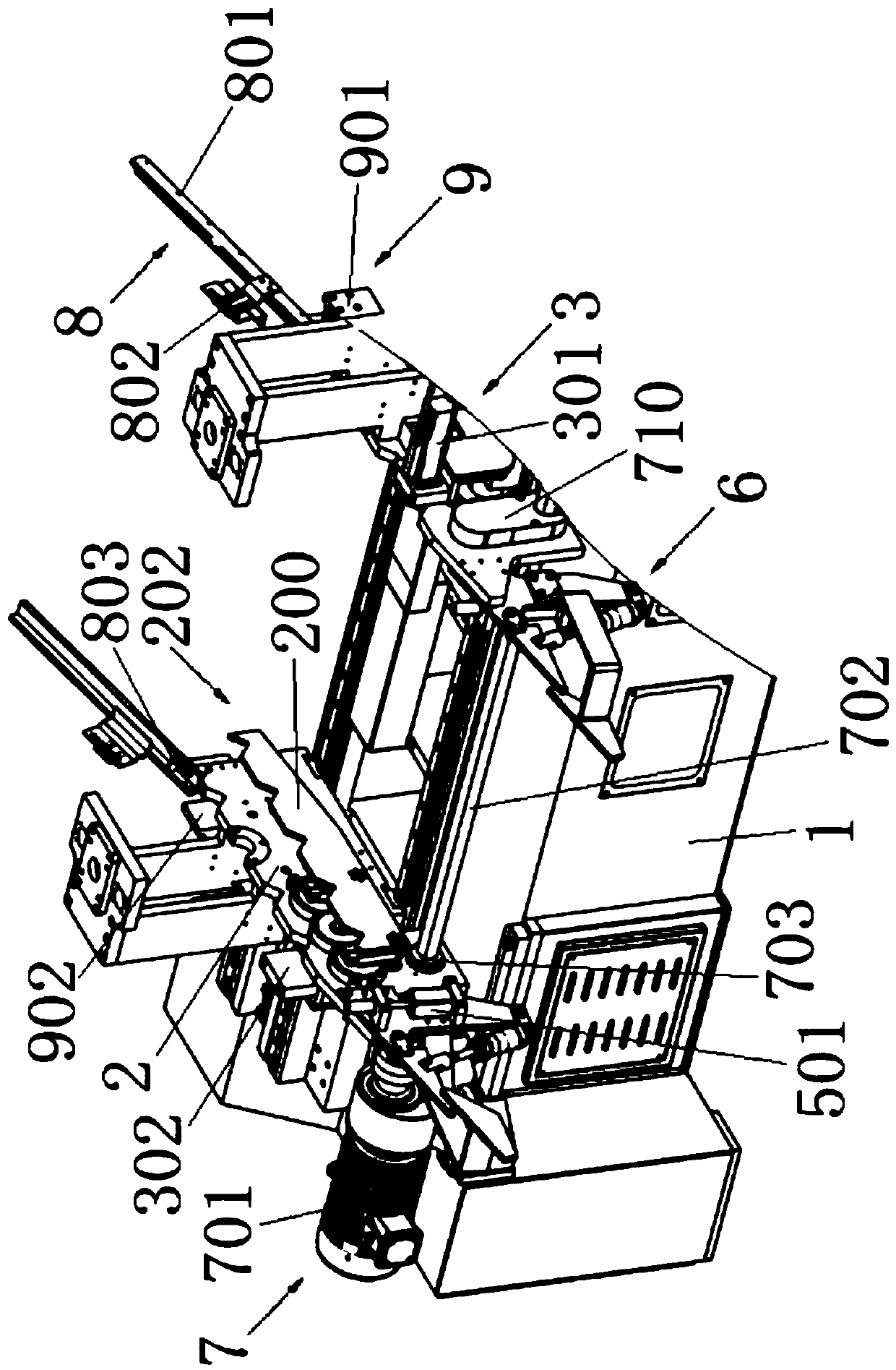
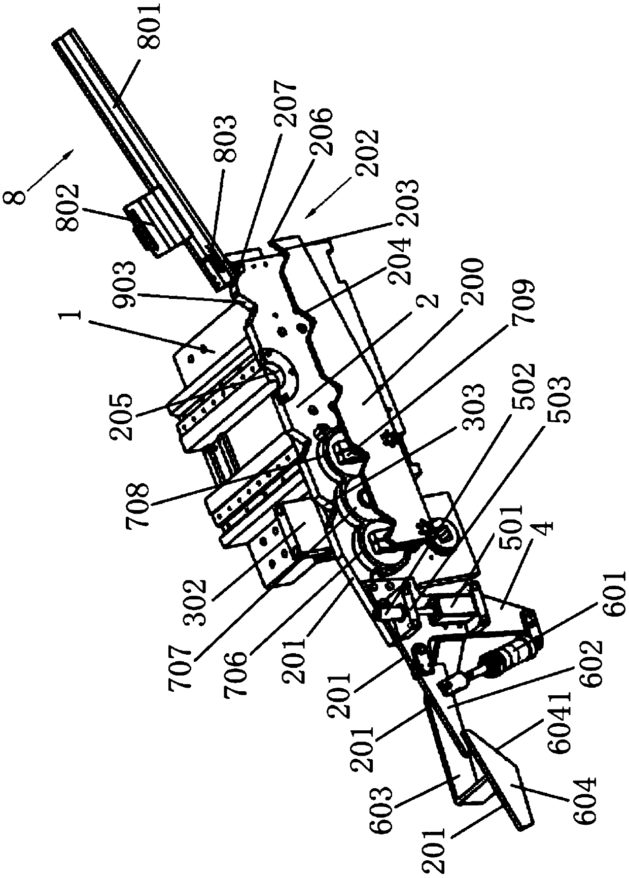
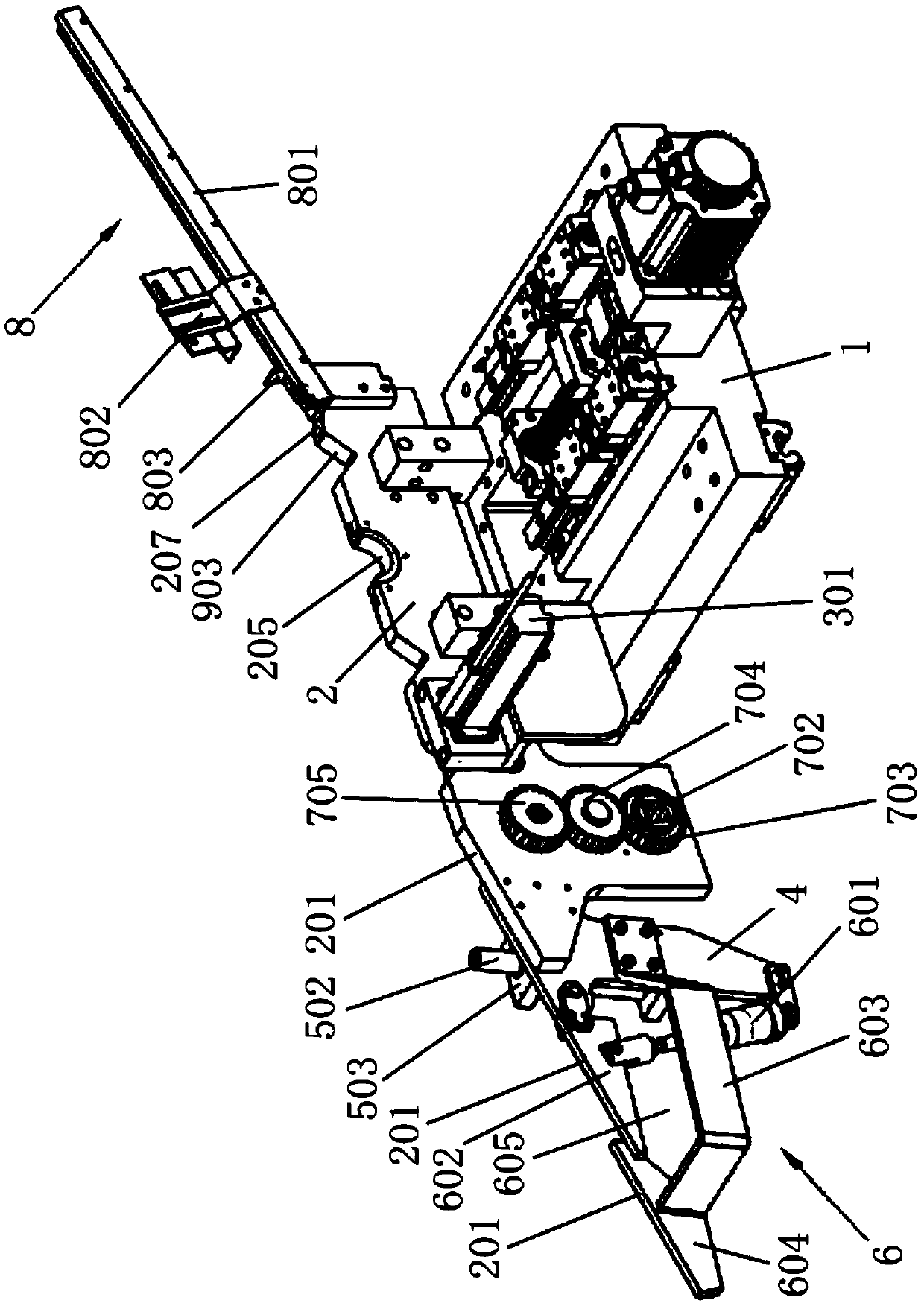
[0046] Such as Figure 1 to Figure 3 As shown together, a feeding device for a pipe end forming machine includes a body 1 on which is provided with two pallets 2 for supporting tube materials, and each pallet 2 is provided with a rotary feeding mechanism There is a feeding mechanism 202, and the two feeding mechanisms 202 are synchronously driven by the same power mechanism 7; the same end of the two pallets 2 is provided with an inclined pipe conveying rack 8, and the other end of the two pallets 2 is provided with a mounting plate 4. The mounting plate 4 is provided with a pipe rejection mechanism 6, each pallet located upstream of the pipe rejection mechanism 6 is provided with a pipe blocking mechanism 5, and pipes are provided between the two pallets 2 located upstream of the pipe blocking mechanism 5 The detection mechanism 3, the top of the two pallets 2 downstream of th...


PUM


Abstract

The invention discloses a feeding device for a pipe end forming machine. The feeding device comprises a machine body provided with two supporting plates. Two rotary feeding mechanisms synchronously driven by the same power mechanism are arranged on the two supporting plates correspondingly. The same ends of the two supporting plates are both provided with inclined pipe conveying brackets, and theother ends of the two supporting plates are both provided with pipe rejection mechanisms. The portion, located on the upstream of the corresponding pipe rejection mechanism, of each supporting plate is provided with a pipe stop mechanism. A pipe detection mechanism is arranged between the portions, located between the two supporting plates, of the upstream of each pipe stop mechanism. Guide conveying parts are arranged on the tops, located on the downstream of the pipe detection mechanisms, of the two supporting plates. The guide conveying parts are inclined towards the pipe stop mechanisms and extend onto the pipe rejection mechanisms. The feeding device realizes automatic feeding of pipes during all the working procedures of a forming machine, online detection of machined pipe ends and rejection of unqualified pipes. The consistency between every two adjacent working procedures is good. The cycle of the pipe end machining and detection working procedures is greatly shortened. The working efficiency is greatly improved.

Description

Technical field [0001] The invention belongs to the technical field of pipe end processing, and in particular relates to a feeding device for a pipe end forming machine. Background technique [0002] At present, after the end processing (such as chamfering, etc.) of the pipe is completed, the pipe needs to be inspected (such as whether the length meets the specified requirements). At this stage, the end processing procedure of the pipe is: first transfer the pipe To the pipe end forming machine, and then finish the pipe end processing on the pipe end forming machine, and then transfer the finished pipe to the inspection station for inspection. At the same time, the unqualified pipes are rejected, And place it with qualified pipes. In this way, there are the following defects: [0003] 1. The pipe is manually transferred to the end processing station, the labor intensity of the workers is high, and the work efficiency is low; or it is transferred to the end processing station throu...

Claims


Application Information

Patent Timeline
Patent Type & Authority Applications(China)
IPC IPC(8): B65G47/74B65G47/88B07C5/34B07C5/36
CPCB65G47/74B07C5/34B07C5/36B65G47/8815B65G2201/0276
Inventor 张海军
Owner 张家港市润泰机械有限公司
Why Eureka
Try Eureka