Heat pump drying room

A technology of heat pump drying and drying room, which is applied in drying, drying machine, tobacco drying, etc., can solve the problems of large flow resistance, loss of flavor substances, and decline in the quality of flue-cured tobacco, so as to reduce the drying air temperature, Uniform drying speed and improved quality of flue-cured tobacco

Pending Publication Date: 2019-04-23
SHANGHAI BOHAN THERMAL ENERGY TECH CO LTD
View PDF0 Cites 0 Cited by
  • Summary
  • Abstract
  • Description
  • Claims
  • Application Information

AI Technical Summary

Problems solved by technology

[0005] 1. Uneven drying
[0006] Taking the drying of tobacco leaves as an example, after the dry air sent by the coal-fired hot air stove in the left heating room enters the drying room, the air flow field is asymmetrical and uneven: near the heating room, the static pressure head of the air flow is small and the dynamic pressure head is large , far away from the heating chamber, the static pressure head of the airflow is large and the dynamic pressure head is small, resulting in uneven airflow field passing through the tobacco leaves and uneven drying speed of the tobacco leaves;
[0007] 2. Large loss of heat leakage
[0008] Since the heating room is placed outside, the heating device is in a high temperature area, and the radiation and convection heat leakage to the environment is serious. The air duct connecting the

Method used


Image

  • Heat pump drying room
  • Heat pump drying room
  • Heat pump drying room

Examples


Embodiment 1

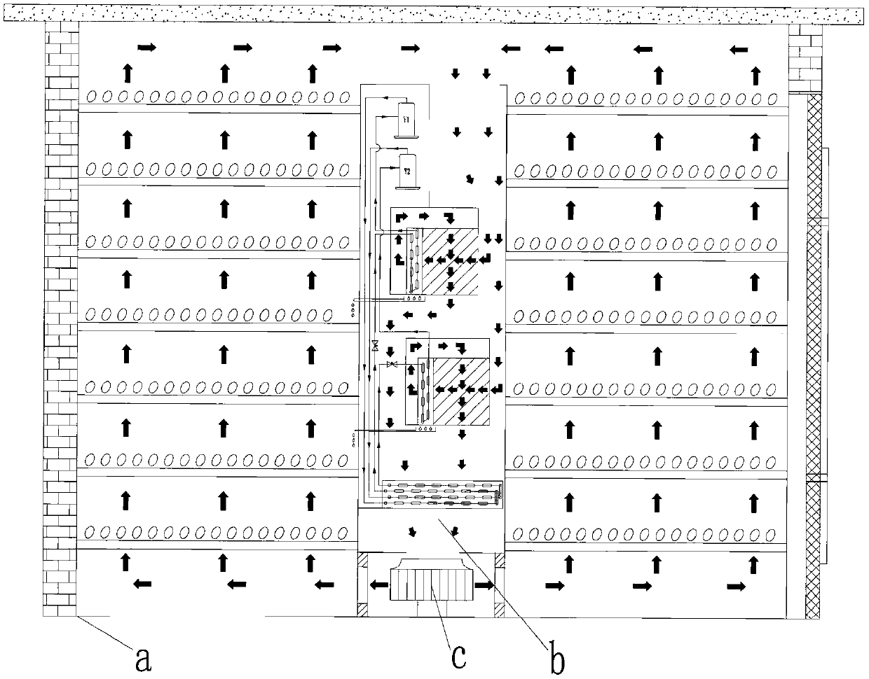
[0070] Referring to 2-5, in this embodiment, the heat pump drying room includes a drying room a, and the drying room a is a drying room with a square cross section. Of course, in other embodiments, the cross-section of the drying house can also be rectangular or other polygonal, which is not limited here.

[0071] In this example, if Figure 3-4 As shown in , a heat pump drying system is set in the center of the drying house a, and the heat pump drying system includes a group of heat pump units b and a centrifugal fan c arranged at the air outlet on the top of the heat pump unit b.

[0072] In this example, refer to Figure 5 In this embodiment, the heat pump unit includes a casing 1, which is a vertical rectangular casing. The housing 1 includes two sets of dehumidification systems, respectively the first dehumidification system and the second dehumidification system; the first dehumidification system includes a sequentially connected compressor 4a, evaporator 5a, throttlin...

Embodiment 2

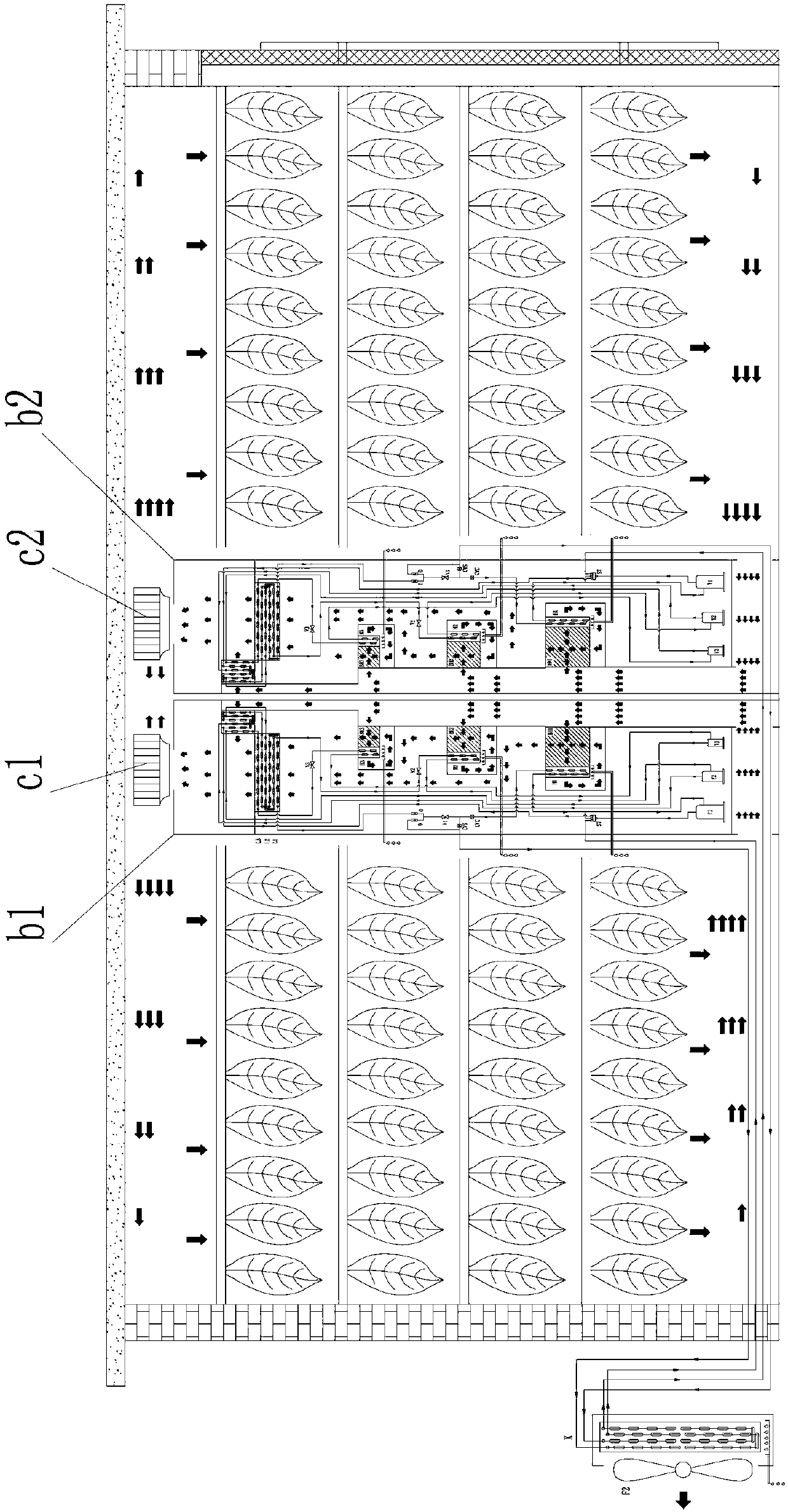
[0079] refer to Figure 6-9 , in this embodiment, a heat pump system is arranged in each drying room a, and each heat pump system includes two sets of heat pump units, which are respectively heat pump unit b1 and heat pump unit b2; heat pump unit b1 and heat pump unit b2 are arranged side by side Set directly at the central position of the drying room a.

[0080] In this embodiment, the heat pump unit b1 and the heat pump unit b2 are provided with air outlets at the upper ends and air inlets at the lower ends, a centrifugal fan c1 is installed at the air outlet at the upper end of the heat pump unit b1, and a centrifugal fan c1 is installed at the air outlet at the upper end of the heat pump unit b2. A centrifugal fan c2 is provided; the high-temperature drying medium produced by the heat pump unit b1 and the heat pump unit b2 diffuses in the centrifugal fan c1 and the centrifugal fan c2 to form a top air bag on the inner top of the drying room a, and then the high-temperature...

Embodiment 3

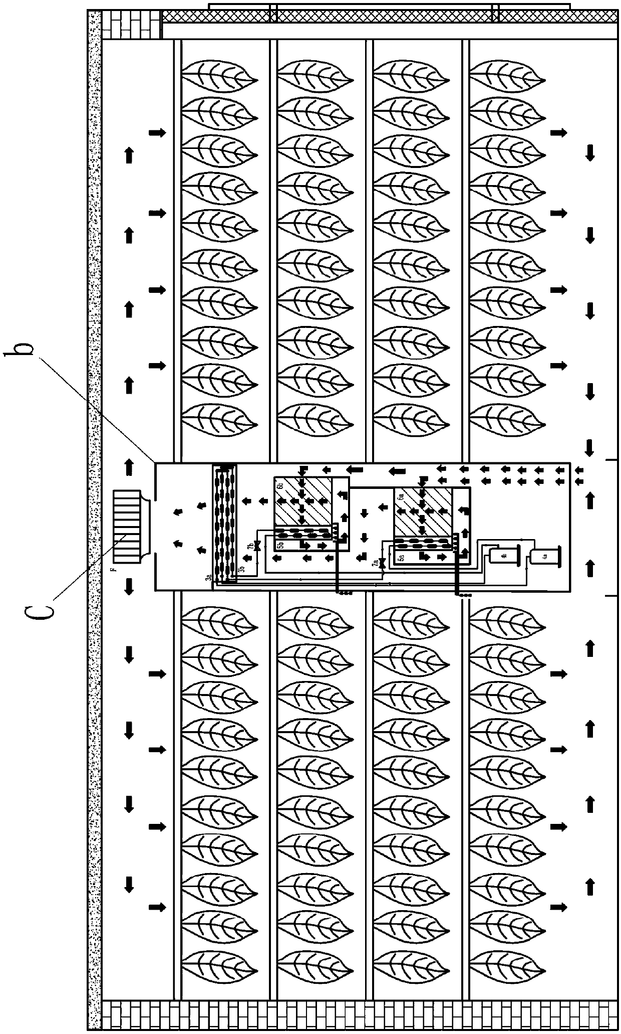
[0095] In the present embodiment, two drying houses are combined into a large drying room.

[0096] Specifically, as shown in 9-10, the drying house a1 and the drying house a2 are arranged side by side and share a partition wall d; in this embodiment, two adjacent drying houses share a heat pump drying system, The heat pump drying system includes a group of heat pump units b and a centrifugal fan c arranged at the air outlet on the top of the heat pump unit b.

[0097] In this embodiment, the heat pump unit b is arranged in the middle of the partition wall d between the drying house a1 and the drying house a2, and the high-temperature dry air generated by the heat pump drying system diffuses around and transports to the two drying houses respectively, such as image 3 shown in .

[0098] For the past ten years, nearly 1.2 million intensive tobacco-curing houses have been built nationwide in accordance with the National Tobacco Banzong (2009) No. 418 Document "Technical Specif...


PUM

PropertyMeasurementUnit
Lengthaaaaaaaaaa

Abstract

The invention discloses a heat pump drying room. The heat pump drying room comprises at least one drying house and at least one set of heat pump drying systems, wherein each set of heat pump drying systems comprises at least one group of heat pump units, and a condenser outlet of each heat pump unit is equipped with a centrifugal fan capable of discharging air by 360 degrees; one set of heat pumpdrying systems is arranged in each drying room, and the centrifugal fan is arranged on the top or the bottom of the middle position of the drying room; high-temperature dried air generated by each heat pump drying system is diffused to the periphery from the top or the bottom of the middle position of the drying room; and adjacent two drying rooms share one set of heat pump drying systems, and thecentrifugal fan is arranged on the top or the bottom of the middle position of a partition wall shared by adjacent two drying rooms; and high-temperature dried air generated by each heat pump dryingsystem is diffused towards the periphery for conveying towards the two drying rooms.

Description

technical field [0001] The invention relates to the technical field of dehumidification device design, in particular to a heat pump drying room. Background technique [0002] In the era when coal, diesel, natural gas and other fossil energy hot blast stoves and biomass particle hot blast stoves are used as heat sources for drying tobacco leaves and agricultural products, the heating room is usually separated from the drying room (baking room) and set outside the drying room; During the dry operation, the high-temperature dry air produced by the hot blast stove is input into the drying room, and after heat and moisture exchange with the wet tobacco leaves, granular agricultural products and other moisture-containing materials in the drying room, it becomes a warm and humid air flow and then discharged out of the drying room; [0003] The heating room is usually separated from the drying room (baking room) and placed outside the drying room, first of all, it is conducive to sa...

Claims


Application Information

Patent Timeline
IPC IPC(8): F26B9/02F26B21/00F26B21/04F26B21/08
CPCF26B9/02F26B21/002F26B21/004F26B21/04F26B21/08F26B2200/22
Inventor 薛世山丁国良诸葛水明崔国民刘彦中叶子豪薛碧荷庄大伟詹飞龙张涛李成伟段兵兵刘玉恩王庆伦
Owner SHANGHAI BOHAN THERMAL ENERGY TECH CO LTD
Why Eureka
Try Eureka