
Cascade LPFG self-filtering sensing system

A sensing system and cascade technology, applied in the field of self-filtering sensing, can solve the problems of restricting the mass production of the sensing system, unstable light source, restricted by cross-sensitivity problems, etc.

Pending Publication Date: 2019-04-23
GUANGXI NORMAL UNIV
View PDF0 Cites 0 Cited by
  • Summary
  • Abstract
  • Description
  • Claims
  • Application Information

AI Technical Summary

Problems solved by technology

[0003] Since LPFG has multiple loss transmission peaks in a longer wavelength range, affected by the ineffectiveness of transmission spectrum superposition, at present, the research on the operation of LPFG as a sensor is more of a single element, and cascade can only be multiple identical The LPFG of the parameters is operated, and the measurement of the physical quantity in the actual environment is seriously restricted by the cross-sensitivity problem, and it is difficult to effectively demodulate and measure the target physical quantity
For the LPFG sensor cascaded with Bragg gratings, although the problem of cross-sensitivity is solved to a certain extent, it is restricted by the reflective data acquisition method and can only perform single-ended operation in the optical fiber communication system, and improper processing of reflected light may easily cause light source Unstable, usually need to match a high-stable broadband light source, resulting in complex and bulky system and high cost, which is not conducive to promotion
In addition, the current research on LPFG sensors focuses on the sensing principle, ignoring the research and proposal of the corresponding matching compatible high-precision and high-speed demodulation methods, which restricts the mass production of the sensing system.

Method used


Image

  • Cascade LPFG self-filtering sensing system
  • Cascade LPFG self-filtering sensing system
  • Cascade LPFG self-filtering sensing system

Examples


Embodiment

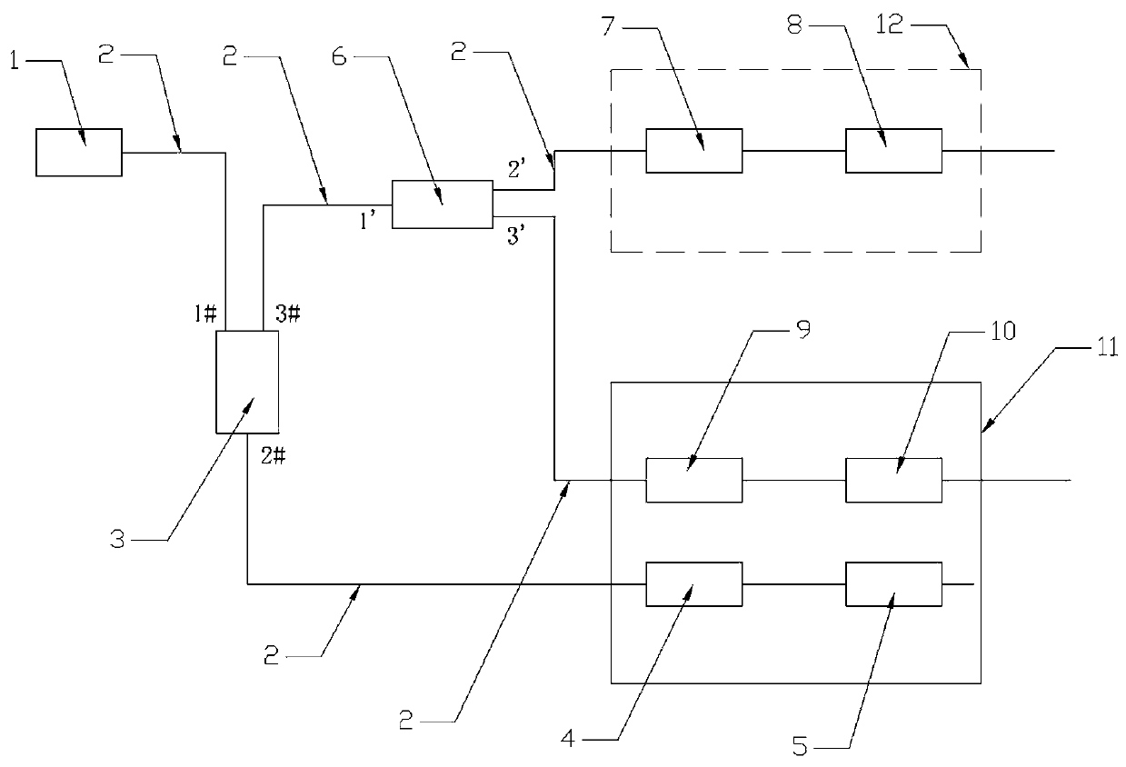
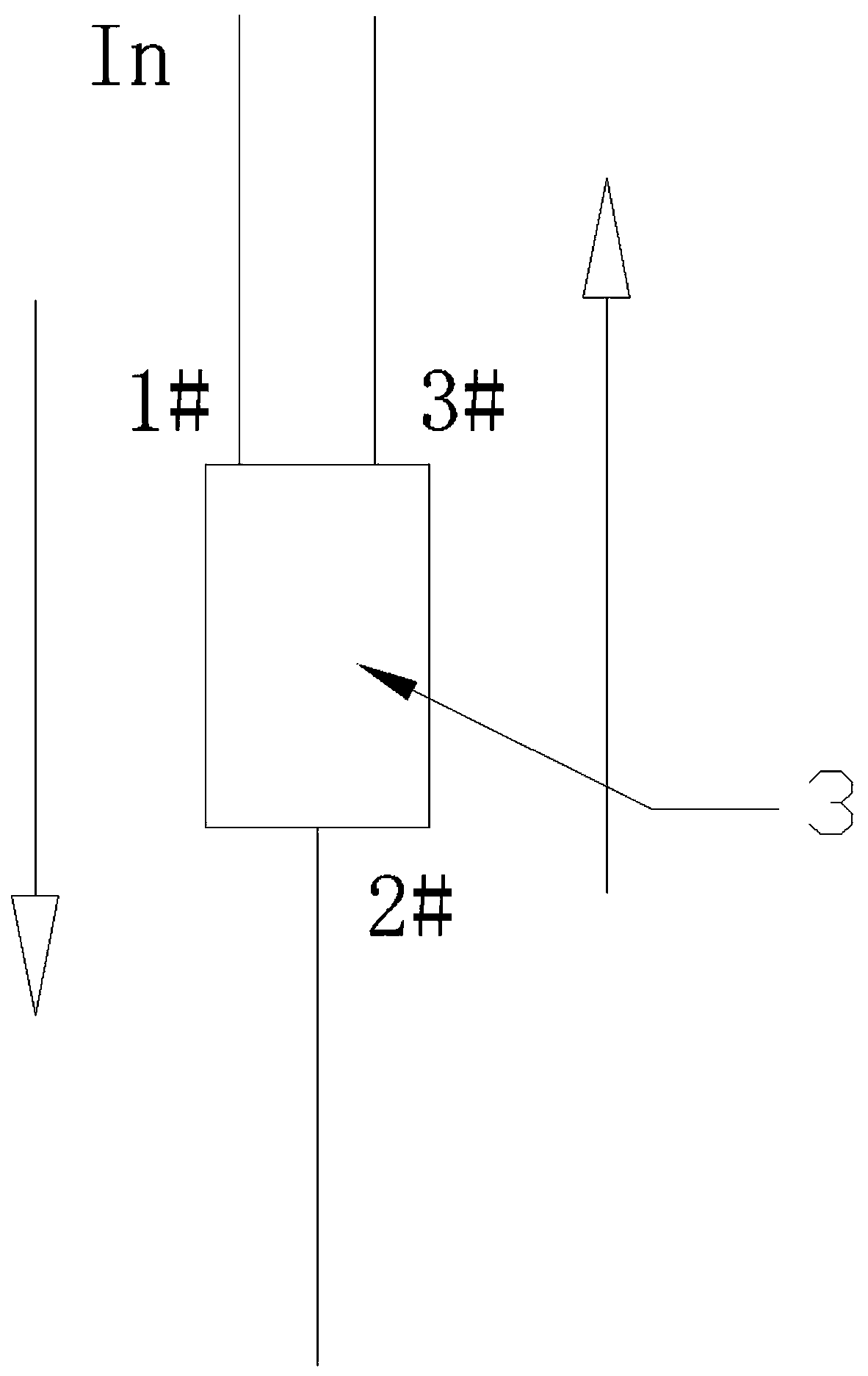
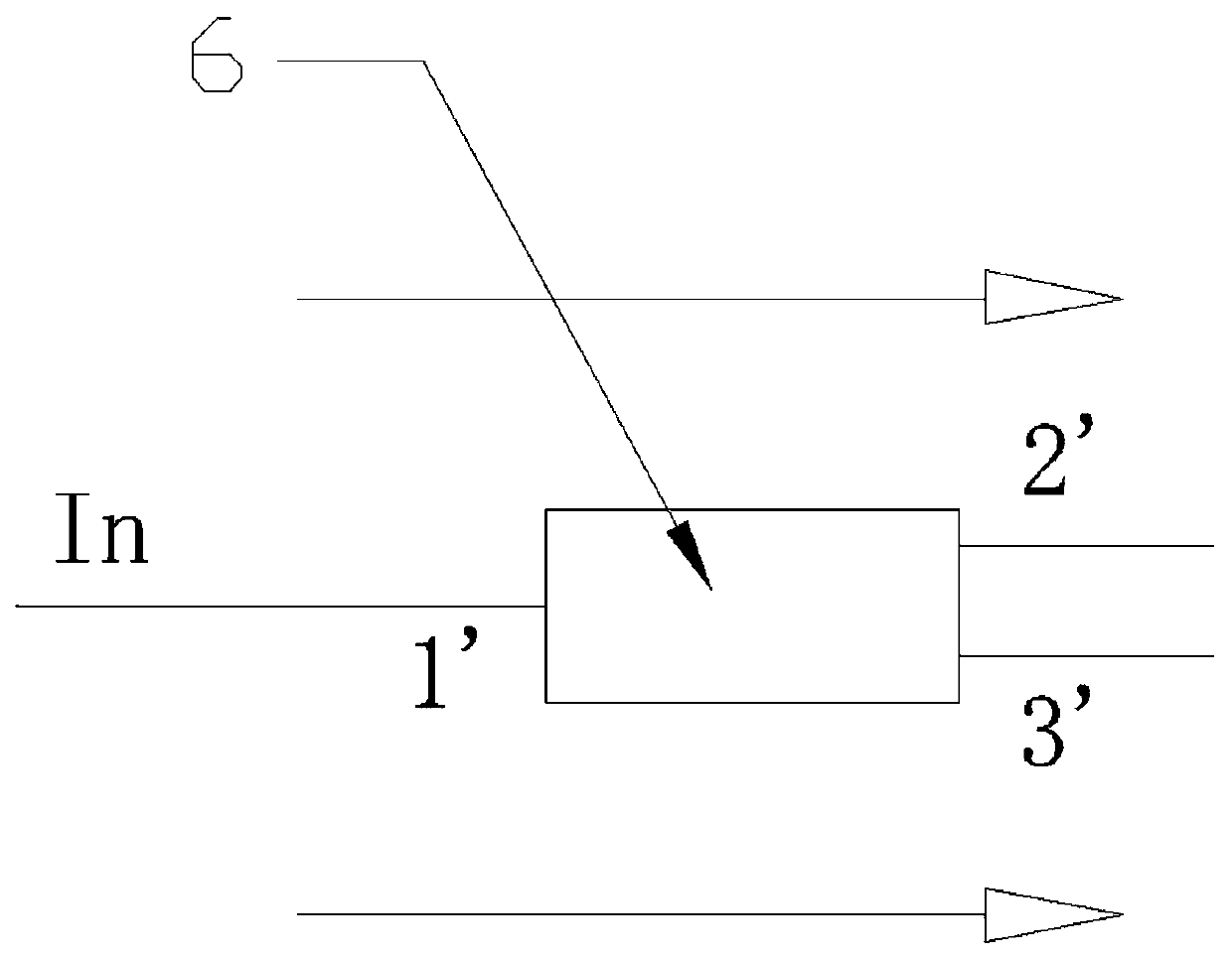
[0029] refer to figure 1 , a cascaded LPFG self-filtering sensing system, including a narrowband light source 1, and a circulator 3 connected to the output end of the narrowband light source 1, such as figure 2 As shown, In is the spectral input, and the direction of the arrow is the direction of light wave transmission. The circulator 3 is provided with a first port 1#, a second port 2# and a third port 3#, wherein the first port 1# of the circulator 3 is connected to the narrowband The output end of the light source 1 is connected, the second port 2# of the circulator 3 is connected to the first FBG4 and the second FBG5 connected in series, and the third port 3# of the circulator 3 is connected to the Y-type coupler 6, such as image 3 As shown, In is the spectral input, the direction of the arrow is the light wave transmission direction, and the Y-type coupler 6 is provided with a first port 1', a second port 2' and a third port 3', wherein the first port 1 of the Y-type c...


PUM

PropertyMeasurementUnit
Sensitivityaaaaaaaaaa
Sensitiveaaaaaaaaaa

Abstract

The invention discloses a cascade LPFG self-filtering sensing system. The cascade LPFG self-filtering sensing system comprises a narrow band light source and a circulator connected with the output endof the narrow band light source, the first port of the circulator is connected with the output end of the narrow band light source, the second port of the circulator is connected with a first FBG anda second FBG which are connected in series, and the third port of the circulator is connected with a Y-shaped coupler. The first port of the Y-shaped coupler is connected with the third port of the circulator, and the second port of the Y-shaped coupler is connected with a first LPFG and a second LPFG which are in cascade connection, and the third port of the Y-shaped coupler is connected with athird LPFG and a fourth LPFG which are in cascade connection. The first FBG, the second FBG, the third LPFG and the fourth LPFG are placed in a constant temperature box, and the first LPFG and the second LPFG are placed in a to-be-detected environment. The sensing system provided by the invention lowers the cost, is high in sensitiveness and linearity, can dynamically achieve strain and temperature measurement simultaneously, improves sensing measurement precision, and is conveniently suitable for spectrum demodulation or high speed demodulation after photovoltaic conversion, the external measuring stability of the system is enhanced, and the application prospect is wide.

Description

technical field [0001] The invention relates to self-filtering sensing technology, in particular to a cascaded LPFG self-filtering sensing system. Background technique [0002] Long Period Fiber Grating (LPFG for short) is a new type of fiber grating that appeared after Fiber Bragg Grating (FBG for short). host. LPFG couples the fiber core waveguide mode matching light wavelength with the cladding waveguide mode, which is lost during the cladding propagation process, thereby avoiding the back coupling of the core waveguide mode, and the spectral bandwidth of the projected loss is much larger than the FBG spectral bandwidth. When the temperature and strain physical quantities to be measured are applied to the LPFG, it will directly cause the change of the physical properties of the optical fiber and the grating, and then cause the red and blue shift of the transmission loss spectrum. By establishing the functional relationship between the transmission loss spectrum drift and...

Claims


Application Information

Patent Timeline
IPC IPC(8): G01B11/16G01K11/32G01K11/3206
CPCG01B11/16G01K11/3206
Inventor 陶维俱吕凤珍胡君辉曾庆科秦子雄
Owner GUANGXI NORMAL UNIV
Learn More