Eureka AIR delivers breakthrough ideas for toughest innovation challenges, trusted by R&D personnel around the world.

Missile-borne single-machine interconnection system

An interconnected system and stand-alone technology, applied in the electronic field, can solve problems such as complex cable connections, and achieve the effects of improving reliability, reducing cable complexity, and reducing production and management costs

Active Publication Date: 2019-04-23
北京航天飞腾装备技术有限责任公司
View PDF5 Cites 3 Cited by
  • Summary
  • Abstract
  • Description
  • Claims
  • Application Information

AI Technical Summary

Problems solved by technology

[0005] The present invention provides a single-machine interconnection system on the fly, to at least solve the technical problem in the related art that complex cable connections are needed when the single-machine interconnection is on the fly

Method used


Image

  • Missile-borne single-machine interconnection system
  • Missile-borne single-machine interconnection system
  • Missile-borne single-machine interconnection system

Examples


Embodiment Construction

[0026] In order to enable those skilled in the art to better understand the solutions of the present invention, embodiments of the present invention will be described below in conjunction with the accompanying drawings.

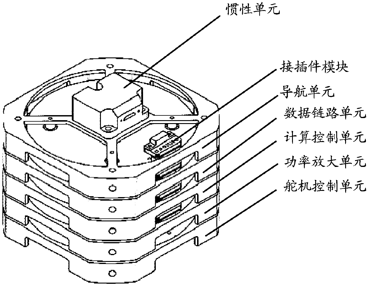
[0027] According to an embodiment of the present invention, a system embodiment of a single-machine interconnection system on a bomb is provided, figure 2 is a schematic diagram of a pop-up stand-alone interconnection system according to an embodiment of the present invention, such as figure 2 As shown, the system includes: stand-alone 1 and interconnection bus 2.

[0028] Wherein, there are multiple stand-alone machines 1, and each stand-alone machine 1 is individually connected to the interconnection bus 2, and the stand-alone machine 1 includes at least one of the following: Global Positioning System GPS (Global Positioning System) receiver, Micro-Electro-Mechanical System MEMS (Micro-Electro-Mechanical System) Mechanical System) inertial group, steerin...


PUM


Abstract

The invention discloses an missile-borne single-machine interconnection system, comprising a plurality of single machines and a group of interconnection buses, each single machine is independently connected to the interconnection bus, the single machine comprises at least one of a GPS (Global Positioning System) receiver, an MEMS (Micro-Electro-Mechanical System) inertial set, a steering engine, abattery, a power source energy storage plate, a fighting part and a guide head, wherein any two single machines in the plurality of single machines are communicated through the interconnection buses,and the effective bandwidth range of an application layer of communication signals is 0 Mbps-12 Mbps. According to the system in the invention, the technical problem that a complex cable connection is required when the missile-borne single machines are interconnected in the prior art is solved.

Description

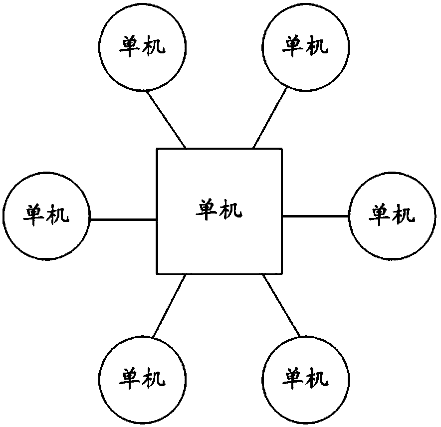
technical field [0001] The invention belongs to the field of electronic technology, and relates to a bullet-on-board single-machine interconnection system. Background technique [0002] At this stage, missile weapons tend to be miniaturized gradually, and in the narrow and long products, the missile-borne electronic system generally adopts a star topology for stand-alone interconnection. figure 1 It is a star topology structure diagram according to the prior art, such as figure 1 As shown, there are intricate cables in the system. However, in related technologies, the use of this topology has exposed many problems in the actual production practice, such as complex design, bulkiness and poor reliability of the interconnection cable on the bullet. These cables not only take up a lot of space on the fly, but also account for a significant weight ratio. The intricate cables bring great inconvenience to the installation of the stand-alone machine, and because of the large numb...

Claims


Application Information

Patent Timeline
Patent Type & Authority Applications(China)
IPC IPC(8): H04L12/40
CPCH04L12/40006H04L2012/40208H04L2012/40215
Inventor 杜明成郭育青王崇李梦馨牛娜郭凯文冯笛恩何俊波周英
Owner 北京航天飞腾装备技术有限责任公司
Why Eureka
Eureka Blog
Learn More