
Mixing arrangement

A technology of mixing device and mixing section, applied in mixers, electric heating devices, mufflers, etc., can solve the problems of non-decomposition, inability to efficiently provide selective catalytic reduction, and ineffective mixing of reactants with exhaust gas, etc. Improve the effect of heat input

Active Publication Date: 2019-04-26
PRIME LTD
View PDF8 Cites 2 Cited by
  • Summary
  • Abstract
  • Description
  • Claims
  • Application Information

AI Technical Summary

Problems solved by technology

Especially at relatively low operating or ambient temperatures or at high dosing rates of the reactants there is the risk that the reactants do not mix efficiently with the exhaust gases or do not decompose and thus cannot efficiently provide the ammonia required for the selective catalytic reduction

Method used


Image

  • Mixing arrangement
  • Mixing arrangement
  • Mixing arrangement

Examples


Embodiment Construction

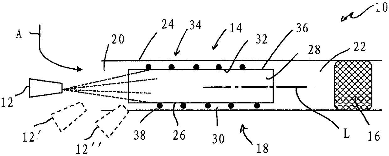
[0039] figure 1 For example, a part of the exhaust system of an internal combustion engine in a vehicle, denoted in its entirety by the reference numeral 10 , is shown in a schematic diagram. The exhaust system 10 includes a reactant outlet 12 , via which a reactant, such as urea / water solution, is added to the exhaust gas A flowing further upstream. Downstream of the reactant discharge device 12 (which is usually also referred to as an injector), there is a mixing device 14 in which the reactant R is mixed with the exhaust gas A. FIG. In this case, the water contained in the reactants R is vaporized and the urea is thermally decomposed, thereby producing ammonia and generally also isocyanic acid, which can be converted further into ammonia in a catalytic reaction with the vaporized water in a pyrolysis reaction. The ammonia produced by the reactants is catalytically converted in the downstream SCR catalyst device 16 in order to reduce the proportion of harmful nitrogen oxide...


PUM


Abstract

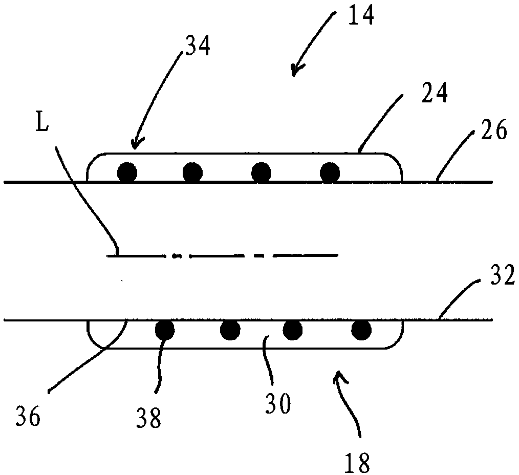
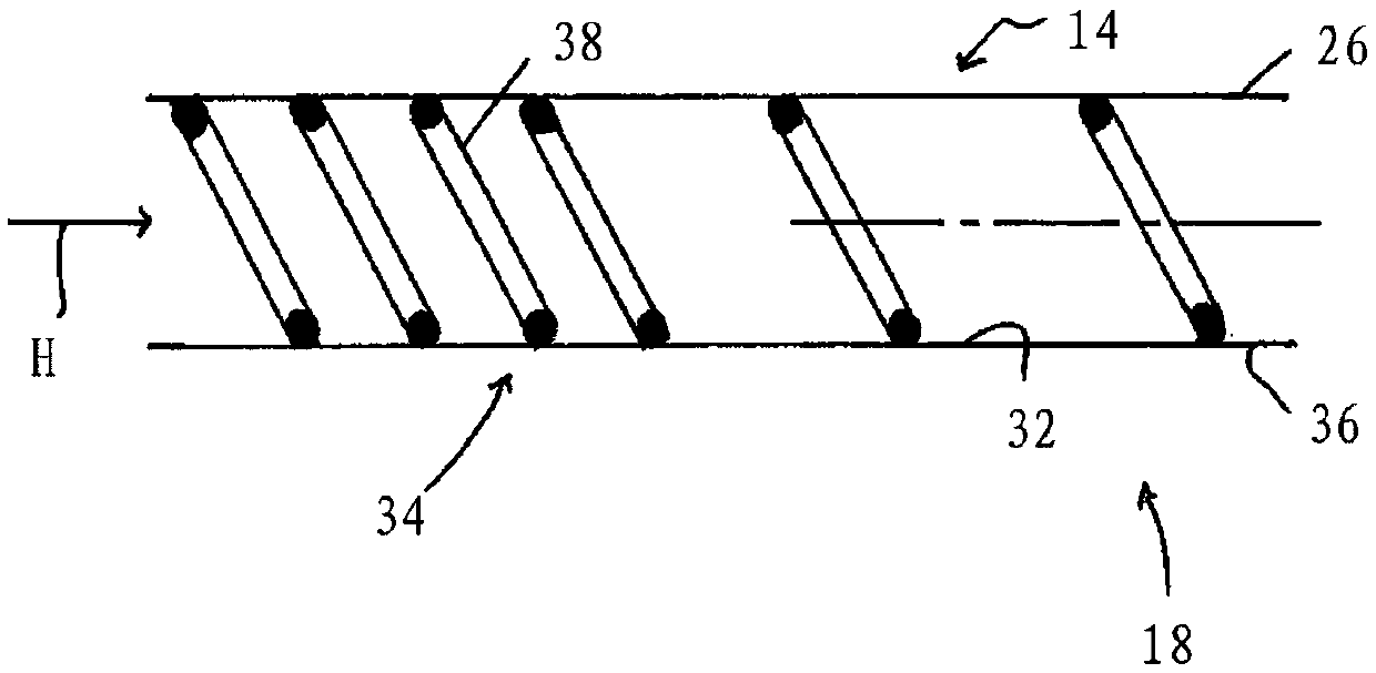
A mixing device for an exhaust system of an internal combustion engine includes a mixing section (14) with a mixing section inlet area (20) to be positioned downstream in relation to a reactant introduction device (12). A mixing section outlet area (22) is positioned upstream in relation to a catalytic converter device (16). The mixing section (14) includes an inner wall (26) surrounding an innervolume (28), through which exhaust gas (A) or / and reactant (R) can flow, and an outer wall (24) surrounding the inner wall (26). An outer volume (30) surrounds the inner volume (28) in a ring-shape, formed between the inner wall and the outer wall (24). An electrically energizable heating device (34) is provided at the inner wall (26), or / and a heat transfer rib formation (54) is provided at the inner wall (26).

Description

technical field [0001] The invention relates to a mixing device for an exhaust system of an internal combustion engine, comprising a mixing section having a mixing section inlet region to be positioned downstream of a reactant outlet device and a mixing zone to be positioned upstream of a catalytic converter device segment exit area. Background technique [0002] DE 10 201 044 A1 discloses an exhaust system for an internal combustion engine in which, over a length section of the exhaust system, a tubular inner wall is surrounded by a likewise tubular outer wall. The inner wall encloses an inner volume through which exhaust gas can flow. An outer volume through which exhaust gas can likewise flow is formed between the inner wall and the outer wall. A vortex generator is provided upstream of the inner wall or upstream of an outer volume formed between the inner wall and the outer wall. The swirl generator imparts a circumferential flow direction component to the exhaust gas...

Claims


Application Information

Patent Timeline
Patent Type & Authority Applications(China)
IPC IPC(8): F01N3/28F01N3/20
CPCF01N3/2013F01N3/2892F01N3/208F01N13/141F01N2240/12F01N2240/25F01N2470/24F01N2610/02F01N2610/102F01N2240/16Y02T10/12B01F35/92B01F2035/99F01N3/2066H05B1/0236H05B1/0297H05B2203/02
Inventor G·盖泽
Owner PRIME LTD
Learn More