Multi-mode optical fiber super-resolution imaging device based on wavefront shaping and light spot correction method thereof

A super-resolution imaging and multi-mode optical fiber technology, applied in the field of super-resolution microscopy, can solve the problems of reducing imaging quality, spot deformation, and limiting the development of super-resolution technology, and achieve the effect of expanding the scope of application

Active Publication Date: 2019-04-26
ZHEJIANG UNIV
View PDF11 Cites 8 Cited by
  • Summary
  • Abstract
  • Description
  • Claims
  • Application Information

AI Technical Summary

Problems solved by technology

[0007] The purpose of the present invention is to provide a multi-mode optical fiber super-resolution imaging device based on wavefront shaping, which solves the existing STED super-resolution imaging system. Aberrations reduce the imaging quality and limit the further development of super-resolution technology in biomedicine

Method used


Image

  • Multi-mode optical fiber super-resolution imaging device based on wavefront shaping and light spot correction method thereof
  • Multi-mode optical fiber super-resolution imaging device based on wavefront shaping and light spot correction method thereof
  • Multi-mode optical fiber super-resolution imaging device based on wavefront shaping and light spot correction method thereof

Examples


Embodiment 1

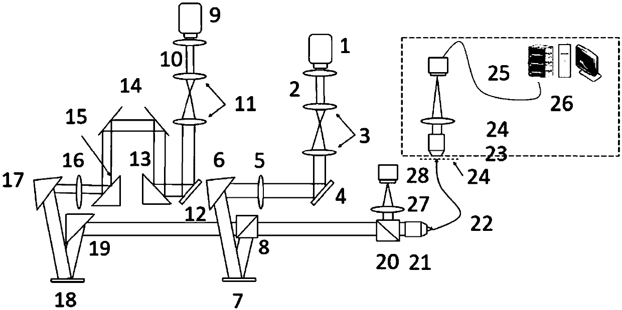
[0036] see figure 1 and figure 2 , the multimode optical fiber super-resolution imaging device based on wavefront shaping of the present embodiment includes the following components:

[0037] A femtosecond laser 1 is used to generate quenched light, and the quenched light is incident on the first polarizer 2;

[0038] The first polarizer 2 is arranged on the outgoing optical path of the femtosecond laser 1, and is used to ensure the linear polarization characteristic of the quenched light;

[0039] The first lens group 3 is arranged on the outgoing light path of the first polarizer 2, and is used to expand the diameter of the quenching light beam;

[0040] The first dispersion modulator 4 is arranged on the outgoing light path of the first lens group 3, and is used for modulating the group velocity dispersion characteristic of the quenched light;

[0041] The first 1 / 2 wave plate 5 is arranged on the outgoing light path of the first dispersion modulator 4 to ensure the modul...

Embodiment 2

[0073] The multimode optical fiber super-resolution imaging device based on wavefront shaping in this embodiment is the same as that in Embodiment 1, and only the light spot correction method is different from Embodiment 1. The spot correction method in this embodiment adopts an iterative optimization method—a closed-loop iterative technique that uses the output signal as a feedback signal in order to increase the gain required by the system, including the following steps:

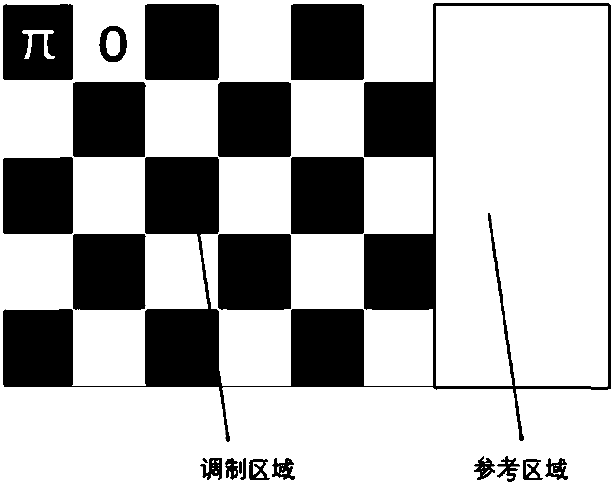
[0074](1) After the excitation light is modulated by the second spatial light modulator 18 in the excitation light optical path, it is coupled to the multimode fiber 22 by the first objective lens 21, and the outgoing light spot is imaged on the camera 25 through the second objective lens 23 and the field lens 24, The camera 25 acquires the light intensity of the target area. Set the Airy patchy light intensity distribution as a beacon, control each pixel block on the second spatial light modulator 18 to i...


PUM


Abstract

The invention discloses a multi-mode optical fiber super-resolution imaging device based on wavefront shaping and a light spot correction method thereof, and belongs to the field of super-resolution microscopy; after quenching light generated by a first laser and excitation light generated by a second laser are injected into a multi-mode optical fiber, the light spot at the exit end of the multi-mode optical fiber is imaged on a camera of a correction system, a modulation signal on a spatial light modulator is continuously converted, the light spot intensity information acquired by the camerais taken as the data base of a multi-mode optical fiber mode correlation correction method to correct the modulated signals of the spatial light modulator, at the exit end of the multi-mode optical fiber, Elie spot-shaped excitation light spots and bread ring-shaped quenching light spots are generated. The quenching light and the excitation light are moved to scan a sample, and the imaging of different depths in the biological tissue sample is achieved by moving the optical fiber, so that the imaging quality reduction caused by scattering in the biological tissue imaging process is overcome, high resolution and large imaging depth are achieved, so that the method is widely applied in biomedicine.

Description

technical field [0001] The invention relates to the field of super-resolution microscopy, in particular to a multi-mode optical fiber super-resolution imaging device based on wavefront shaping and a light spot correction method thereof. Background technique [0002] Optical microscopy has long been an important tool in biomedical research due to its non-contact and non-invasive advantages. However, since 1873, it has been believed that the resolution limit of the optical microscope is about 200nm, which cannot be used to clearly observe biological structures within 200nm in size. Super-resolution Optical Microscopy (Super-resolution Optical Microscopy) is the most significant breakthrough in the field of optical microscopic imaging in this century, breaking the resolution limit of optical microscopy (in other words, exceeding the resolution limit of optical microscopy, so it is called super-resolution optical microscopy. Imaging), providing unprecedented tools for life scie...

Claims


Application Information

Patent Timeline
Patent Type & Authority Applications(China)
IPC IPC(8): G02B27/58G02B23/24G02B23/26G02F1/01G01N21/01G01N21/19
CPCG01N21/01G01N21/19G01N2021/0112G01N2201/127G02B23/2469G02B23/26G02B27/58G02F1/0121
Inventor 马耀光文仲杨青刘旭
Owner ZHEJIANG UNIV
Why Eureka
Try Eureka