Hologram generation method and system based on light field renderin, storage medium and near-to-eye AR holographic three-dimensional display system

A hologram, light field image technology, applied in optics, optical components, instruments, etc., can solve the problems of long calculation time and large amount of calculation, and achieve the effect of less amount of calculation, small amount of calculation, and fast calculation speed.

Active Publication Date: 2019-04-26
LIGHTIN INC
View PDF9 Cites 7 Cited by
  • Summary
  • Abstract
  • Description
  • Claims
  • Application Information

AI Technical Summary

Problems solved by technology

[0007] The above three hologram generation methods all face the problems of large amount of calculation and long calculation time. Real-tim...

Method used


Image

  • Hologram generation method and system based on light field renderin, storage medium and near-to-eye AR holographic three-dimensional display system
  • Hologram generation method and system based on light field renderin, storage medium and near-to-eye AR holographic three-dimensional display system
  • Hologram generation method and system based on light field renderin, storage medium and near-to-eye AR holographic three-dimensional display system

Examples


Embodiment 1

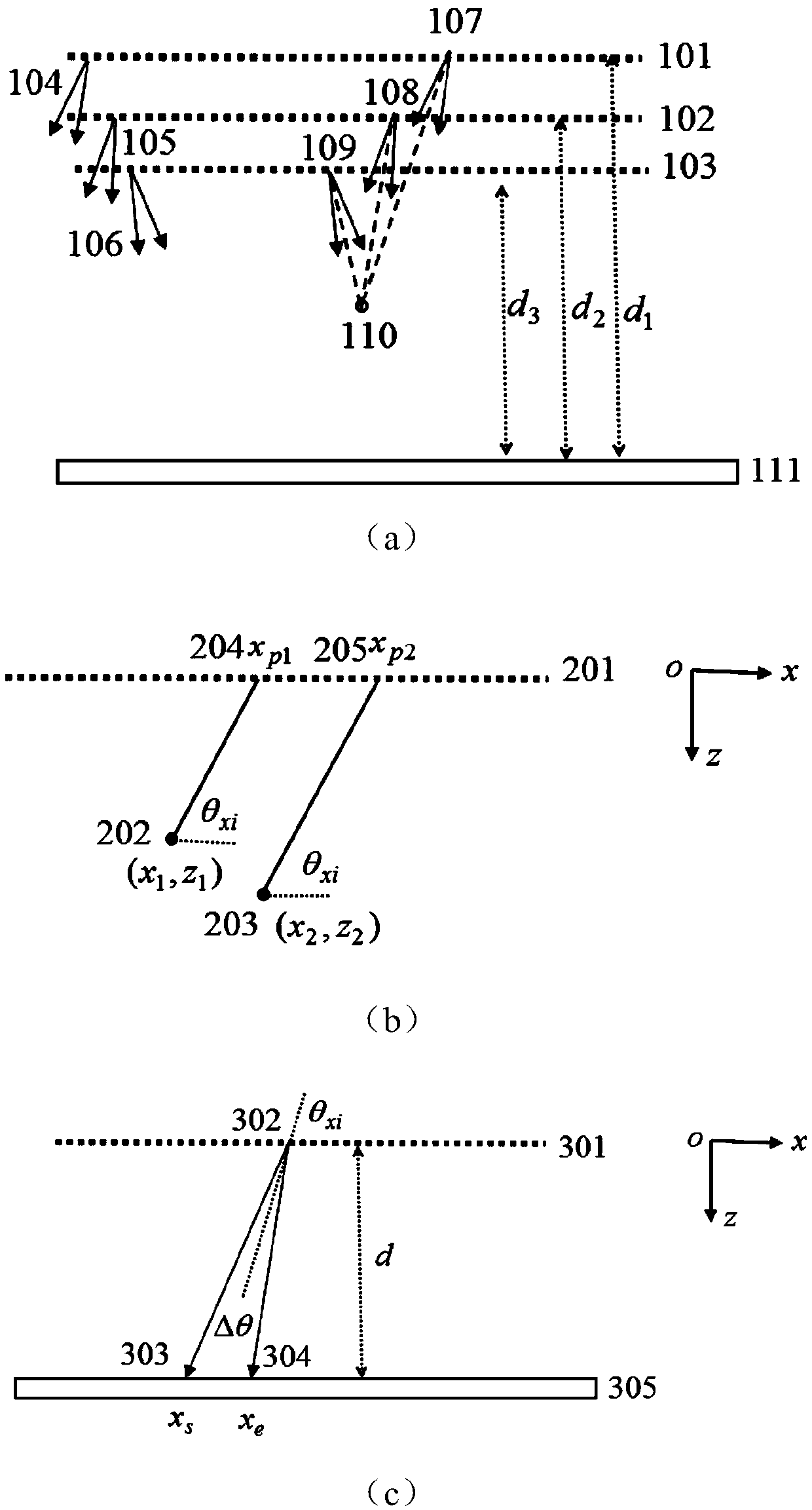
[0069] This embodiment gives a hologram generation method based on light field rendering, and its generation principle is as follows figure 1 As shown, where (a) is the hologram generation principle of light field rendering, where 101, 102, and 103 are three light field rendering planes, and on one light field rendering plane, the light-emitting angle and light-emitting direction of each point are the same, Different light-field rendering planes have the same light-emitting angle but different light-emitting directions. 104, 105, and 106 represent the light-emitting angles and directions of the three light-field rendering planes, respectively. 110 is a point in space, which is a common area formed by overlapping small-angle light waves emitted by three light-emitting points 107 , 108 , 109 on light field rendering planes 101 , 102 , 103 . 111 is a holographic plane, which will record the complex amplitude of the light field transmitted from the light field rendering plane to t...

Embodiment 2

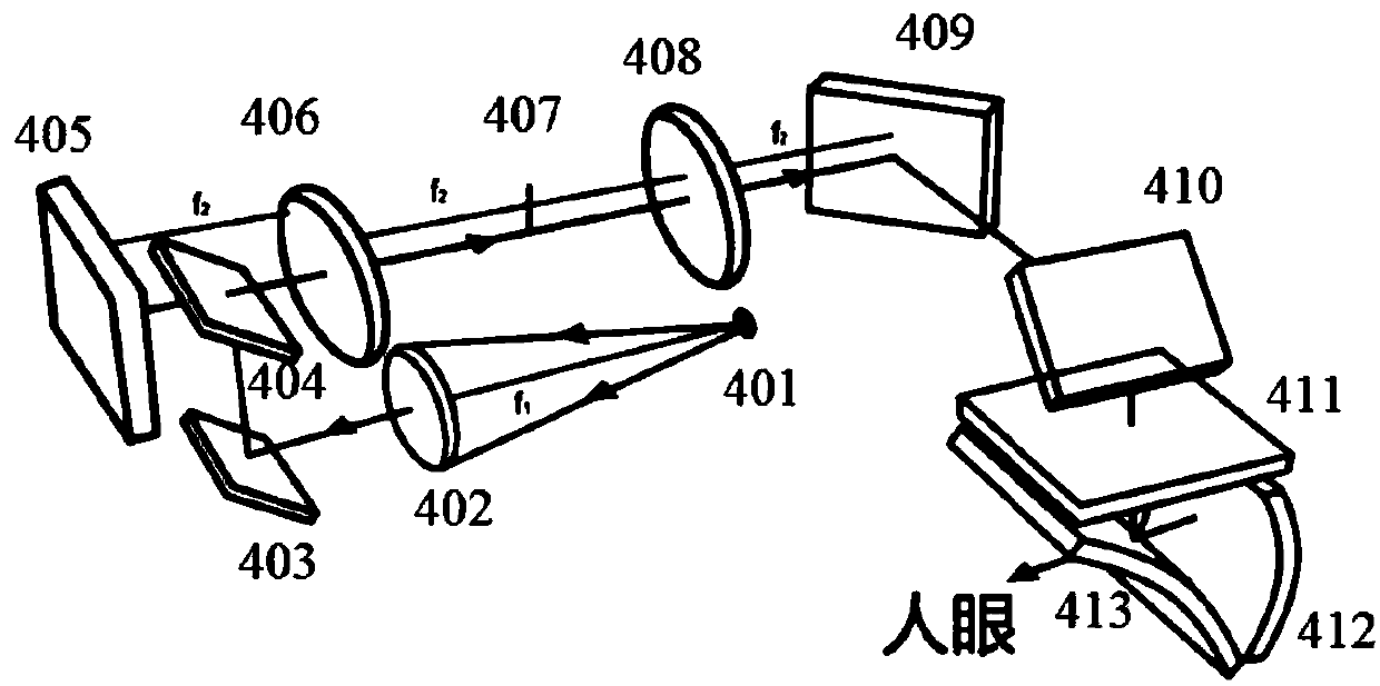
[0090] figure 2 It is a schematic diagram of the near-eye AR holographic three-dimensional display system of this embodiment. Among them, 401 is the light source, which can be a single-color LED light source or a laser light source, or a three-color LED or laser light source coupled into the optical fiber, lighted in time-sharing, and emits divergent spherical waves at the optical fiber port. The divergent spherical wave emitted by the light source is collimated into a plane wave after passing through the lens 402, reflected by the reflector 403 and then partially reflected by the half-mirror 404, and the reflected light illuminates the spatial light modulator 405, which is reflective Amplitude type or phase type LCOS, the hologram is loaded into LCOS by computer, the computer is not shown in the figure. The light field modulated by LCOS is back diffracted, after passing through the lens 406, a spectrum is formed at the focal plane 407 of the lens 406, and a filter (not show...

Embodiment 3

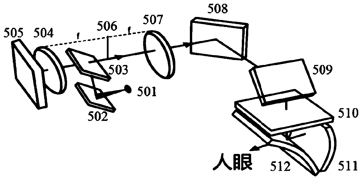
[0092] image 3 It is a schematic diagram of the near-eye AR holographic three-dimensional display system of this embodiment. Among them, 501 is the light source, which can be a single-color LED light source or a laser light source, and can be a three-color LED or laser light source coupled into the optical fiber, lighted in time-sharing, and emits divergent spherical waves at the fiber port. The divergent spherical wave emitted by the light source is reflected by the reflector 502 and then partially reflected by the half-mirror 503. The reflected light is collimated by the lens 504 and becomes a plane wave to illuminate the spatial light modulator 505. The spatial light modulator 505 is a reflective amplitude type Or phase-type LCOS, the hologram is loaded into the LCOS by a computer, which is not shown in the figure. The light field modulated by LCOS is back diffracted, and after passing through the lens 504, a spectrum is formed at the focal plane 506 of the lens 504, and ...


PUM


Abstract

The invention discloses a hologram generating method and system based on light field renderin, a storage medium and a near-to-eye AR holographic three-dimensional display system. The hologram generating method comprises the steps that (1) at least two light field renderin planes are constructed, and each light field renderin plane is composed of a plurality of luminous points; (2) three-dimensional point cloud data of a three-dimensional object separately render to the different light field renderin planes, and a light field image of each light field renderin plane is obtained; (3) the light field images of the light field renderin planes and the point spread function of the light field images on a holographic surface are subjected to convolution to obtain complex amplitudes of the light field images on the holographic surface; and (4) the complex amplitudes of the light field images of all light field renderin planes on the holographic surface are subjected to superposition, then reference light interference calculation is introduced for encoding to obtain a hologram of the three-dimensional object. The hologram generation method has a high calculation speed and can realize real-time rapid hologram generation.

Description

technical field [0001] The present invention relates to the field of holographic three-dimensional display, in particular to a hologram generation method, system, storage medium and near-eye AR holographic three-dimensional display system based on light field rendering. Background technique [0002] At present, near-eye AR three-dimensional display is an important research field and application field. There are many ways to realize near-eye AR three-dimensional display, such as using microdisplay and complex eyepiece system to realize AR three-dimensional display. Binocular parallax 3D display has convergence conflicts. Wearing this kind of AR 3D display device will cause eye fatigue and dizziness, which will have a certain adverse effect on the visual development of teenagers, so it is not suitable for teenagers to wear. [0003] Compared with the complex eyepiece system, when using optical waveguide and coupling grating technology to realize near-eye AR three-dimensional d...

Claims


Application Information

Patent Timeline
IPC IPC(8): G03H1/04G02B27/01
CPCG02B27/0101G02B2027/0105G02B2027/0109G03H1/0465
Inventor 杨鑫王帆魏一振
Owner LIGHTIN INC
Why Eureka
Try Eureka