A Miniaturized Ultra-Wideband Planar Band-Stop Filter

A planar band and filter technology, applied to waveguide devices, circuits, electrical components, etc., can solve the problems of complex implementation, increase in device size, and large amount of calculation, and achieve the effect of small size and band-stop band

Active Publication Date: 2019-11-12
NANJING UNIV OF POSTS & TELECOMM
View PDF6 Cites 0 Cited by
  • Summary
  • Abstract
  • Description
  • Claims
  • Application Information

AI Technical Summary

Problems solved by technology

[0004] The traditional planar band-stop filter generally adopts the method of cascading open-circuit stubs, and its relative bandwidth increases with the increase of the number of stages, which inevitably increases the size of the device. For example, the fourth-order band-stop filter requires four quadruple One-quarter-length open-circuit stubs (approximately one-quarter waveguide wavelength in length in the non-propagating direction), and three quarter-wavelength admittance transformers (approximately three-quarter waveguide wavelength in length in the propagating direction) , the relative bandwidth achieved is about 50% to 70% (the insertion loss in the stop band is higher than 20dB).
From the above analysis, it can be seen that miniaturization and ultra-wideband planar band-stop filters are the direction of future development. However, how to achieve ultra-wideband band-stop characteristics and good stop-band suppression through small size and simple structure, now Still a design pain point and challenge

Method used


Image

  • A Miniaturized Ultra-Wideband Planar Band-Stop Filter
  • A Miniaturized Ultra-Wideband Planar Band-Stop Filter
  • A Miniaturized Ultra-Wideband Planar Band-Stop Filter

Examples


Embodiment Construction

[0024] The present invention will be further described in detail below in conjunction with the embodiments and the accompanying drawings, but the embodiments of the present invention are not limited thereto.

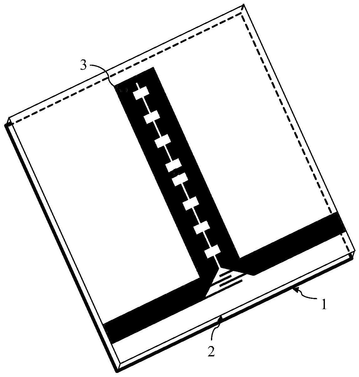
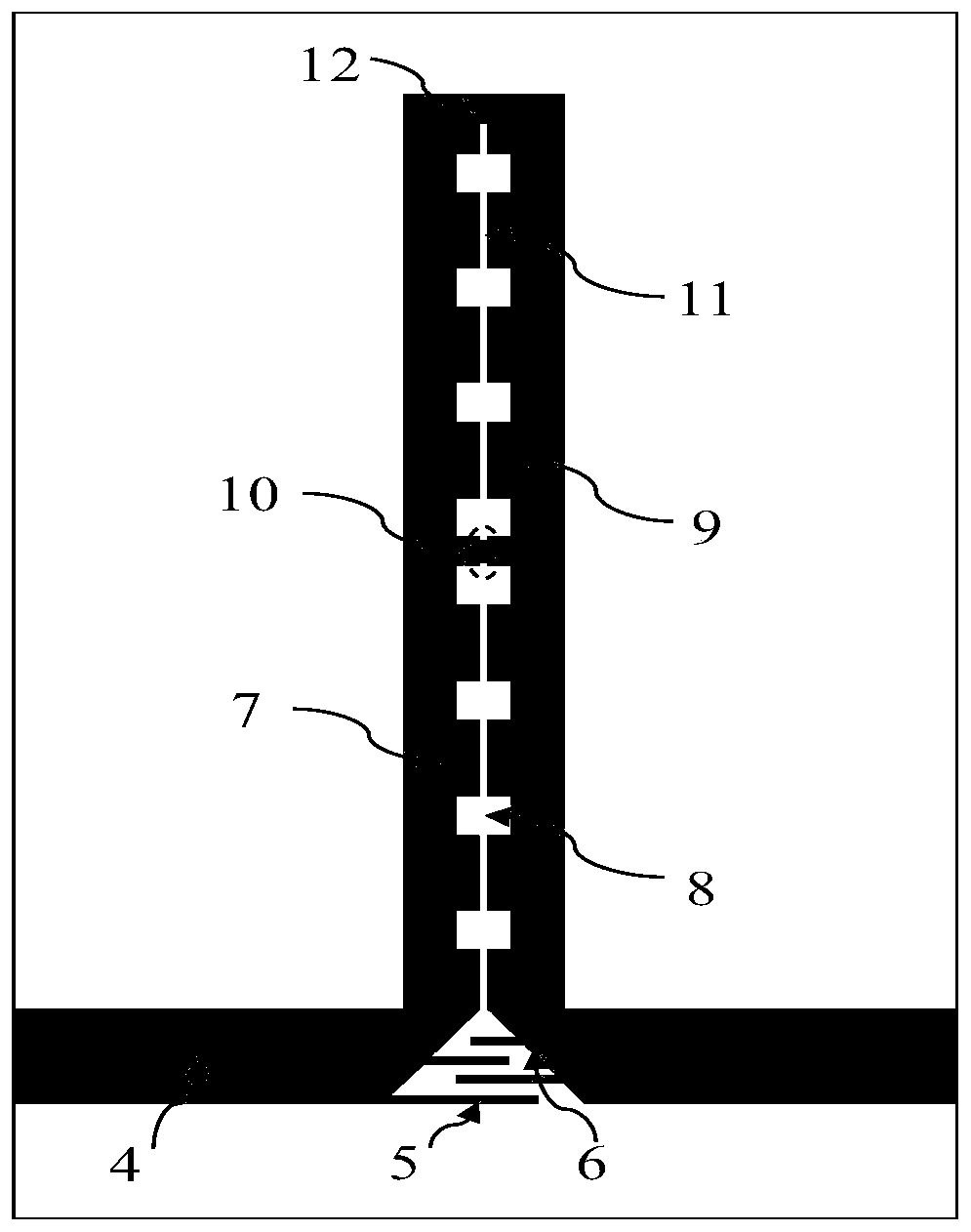
[0025] Such as figure 1 As shown, a miniaturized ultra-wideband planar bandstop filter disclosed in the embodiment of the present invention includes a grounded metal plate 1 at the bottom, a microstrip dielectric plate 2 at the middle layer, and a metal microstrip line 3 and chip capacitor on the upper layer. 10 constitute the circuit structure. Such as figure 2 As shown, the metal microstrip line 3 includes a first coupled line 7 , a second coupled line 9 , an interdigitated port capacitor 5 and a pair of input / output feeder lines 4 with tapered ports. A pair of input / output feeder lines 4 are on the same central line, the ends of the two coupling lines 7 and 9 are connected, and the other ends are respectively connected to the transition ends 6 of the feeder lines 4...


PUM


Abstract

The invention discloses a miniaturized ultra-wideband planar bandstop filter, which includes metal microstrip lines and chip capacitors in the upper layer, a microstrip dielectric plate in the middle layer, and a grounded metal floor at the bottom; wherein the metal microstrip line includes A pair of symmetrical input / output feeders, interdigitated port capacitors, first and second ladder impedance coupling lines, chip capacitors are loaded across the short-circuited coupling lines. The two coupled lines are respectively connected to the transition ports of the input / output feeder, and both are perpendicular to the feeder. By changing the length and interval of the port capacitor fingers to adjust the size of the port capacitance, and then change the number or position of transmission zeros in the stop band, and change the positions of two low-frequency transmission zeros in the stop band by changing the patch capacitance value. Compared with the prior art, the invention has a small size and has the characteristics of an ultra-wide stop band, and can be well applied in a broadband system.

Description

technical field [0001] The invention relates to a miniaturized ultra-broadband planar band-stop filter, which belongs to the field of microwave technology and can be used in broadband receiving systems and applications for suppressing microwave interference signals. Background technique [0002] Band-stop filters play an important role in modern wireless communication systems. They are mainly used to suppress unwanted signals in communication systems. For example, when high-power amplifiers are saturated, they will contain second harmonics, which can affect the subsequent The circuit generates interference, so that the useful signal will be distorted. Therefore, the band stop filter plays an important role for high attenuation of the specified frequency band. [0003] The miniaturization, wide stop band and planar characteristics of the band stop filter promote its application. With the increasingly high-density integration of future devices, the miniaturization of devices...

Claims


Application Information

Patent Timeline
IPC IPC(8): H01P1/203
CPCH01P1/20381
Inventor 吕云鹏刘宝光祝雷程崇虎
Owner NANJING UNIV OF POSTS & TELECOMM
Why Eureka
Try Eureka