Fiber laser and laser material processing system

A fiber laser, fiber laser technology, applied in lasers, laser parts, phonon exciters, etc., can solve the problems of complex manufacturing coupling process, high implementation cost, ring-core multi-clad fiber, etc., to achieve cross-sectional characteristics, The production process is simple and the effect of change is achieved

Pending Publication Date: 2019-04-26
SHENZHEN JPT OPTO ELECTRONICS CO LTD
0 Cites 1 Cited by

AI-Extracted Technical Summary

Problems solved by technology

[0004] The purpose of the present invention is to provide a fiber laser and a laser material processing system including the fiber laser, to solve the problem of changing the beam profile chara...

Method used

A plurality of light guide columns 4 of the present invention realize required arrangement through outer cover light guide column cover 5 or machine-added parts in the laser output head, after being arranged, can pass through machinery, gluing, heat adhesion or CO2 laser melting etc. To fix all the light guide columns 4 to ensure the stable output of the system.
Referring to Fig. 3 and shown in Fig. 4, another kind of fiber laser is provided for the present embodiment, and it comprises three fiber laser modules 1, wherein two fiber laser modules 1 are each connected with a secondary light guide column, and another optical fiber The laser module 1 is connected with the main beam. The fiber laser of this embodiment adds auxiliary light guide columns around or next to the main light column, which can reduce spatter and homogenize the molten pool, so the output beam of the fiber laser can effectively improve the welding effect.
The embodiment of the present application is by the spatial arrangement of a plurality of light guide posts 4, and a plurality of light guide posts 4 are connected with one or more fiber laser modules 1 aga...

Abstract

The invention discloses a fiber laser and a laser material processing system. The fiber laser includes a laser output head and a plurality of fiber laser modules, the laser output head includes a plurality of light guiding columns which are arranged in parallel in space, each light guiding column corresponds to a transmission fiber and is connected to one of the multiple fiber laser modules through the transmission fiber, and by controlling or distributing the output power of different fiber laser modules, the profile characteristics of output beams of the light guiding columns are adjusted orchanged. According to the fiber laser and the laser material processing system, through spatial arrangement of the multiple light guiding columns, the light guiding columns are connected with one ormore fiber laser modules, and the profile characteristics of the output beams are changed; and by changing the output power of the corresponding fiber laser modules, required output light spot distribution can be obtained, continuous and real-time adjustment of output light spots can be achieved, the implementation scheme is flexible and diverse, the manufacturing process is relatively simple, andthe manufacturing cost can be effectively lowered.

Application Domain

Technology Topic

Laser fiberOptoelectronics +7

Image

  • Fiber laser and laser material processing system
  • Fiber laser and laser material processing system
  • Fiber laser and laser material processing system

Examples

  • Experimental program(4)

Example Embodiment

[0063] Example 1
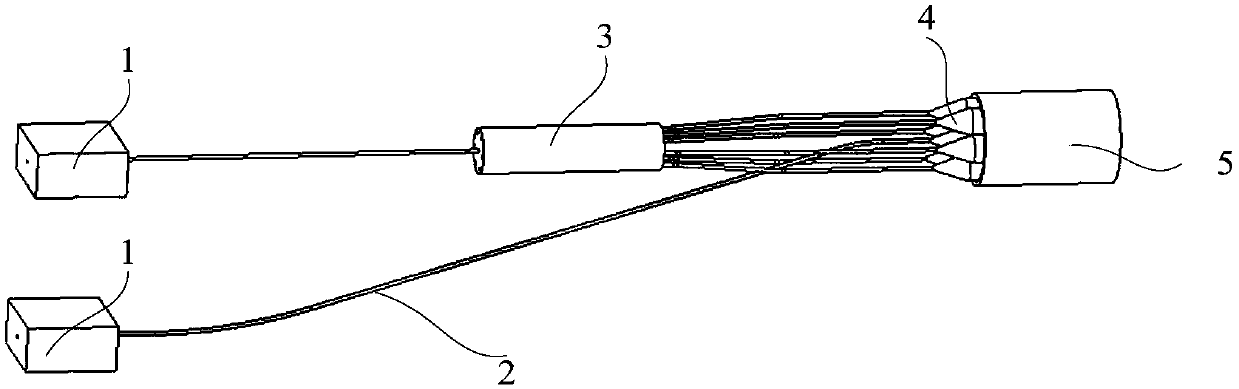
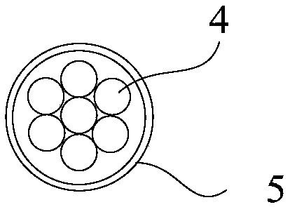
[0064] Please refer to figure 1 and figure 2 As shown, a fiber laser is provided in this embodiment, and seven cylindrical light guide columns 4 are closely arranged in a circle, that is, one light guide column 4 in the middle, and the other six light guide columns 4 closely surround the middle light guide column 4 in the circumferential direction. Arranged, the pigtails of the seven light guide columns 4 can be connected to different fiber laser modules 1, or some of the light guide columns 4 pigtails can be connected to a certain fiber laser module 1, and the laser power of each fiber laser module 1 can be separately The control can also control several or all of them synchronously, so as to realize the change or control of the output light spot characteristics.
[0065] For example, the output laser power of the middle light guide column 4 can be individually controlled, and at the same time, the output laser power of the six light guide columns 4 in the circumferential direction can be controlled uniformly. The output light spot can be changed into a Gaussian energy distribution, a ring-shaped spot distribution, or a quasi-flat-top energy spot distribution; if necessary, each light guide column 4 can also be connected to fiber laser modules with different wavelengths 1, or form multiple combinations, that is, some of the light guide columns 4 are connected to a certain fiber laser module 1 of the same wavelength, so as to realize some special applications.

Example Embodiment

[0066] Embodiment 2
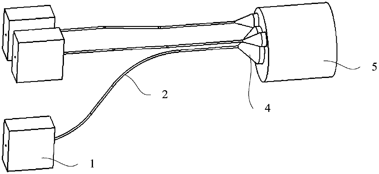
[0067] refer to image 3 and Figure 4 As shown, another fiber laser is provided in this embodiment, which includes three fiber laser modules 1, wherein two fiber laser modules 1 are each connected to a secondary light guide column, and the other fiber laser module 1 is connected to the main light column. In the fiber laser of this embodiment, auxiliary light guide columns are added around or beside the main light column, which can reduce spatter and homogenize the molten pool, so the output beam of the fiber laser can effectively improve the welding effect.

Example Embodiment

[0068] Embodiment 3
[0069] refer to Figure 5 As shown, another fiber laser provided in this embodiment includes seven fiber laser modules 1 , and each fiber laser module 1 is connected to a light guide column 4 respectively.

PUM

no PUM

Description & Claims & Application Information

We can also present the details of the Description, Claims and Application information to help users get a comprehensive understanding of the technical details of the patent, such as background art, summary of invention, brief description of drawings, description of embodiments, and other original content. On the other hand, users can also determine the specific scope of protection of the technology through the list of claims; as well as understand the changes in the life cycle of the technology with the presentation of the patent timeline. Login to view more.

Similar technology patents

Wristband type laser therapy instrument

PendingCN109157759AAchieve changeEnable connectivityLight therapyWristTreatment effect
Owner:ZHENGAN BEIJING MEDICAL EQUIP

Anode phosphorus copper with variable area and application method thereof

InactiveCN104694999ARealized areaAchieve changeElectrodesCopperArea change
Owner:东又悦(苏州)电子科技新材料有限公司

Data augmentation method based on RBSAGAN

PendingCN112668424AOvercoming incomplete feature informationAchieve changeCharacter and pattern recognitionNeural architecturesDeconvolutionData set
Owner:BEIJING UNIV OF TECH

Base with adjustable inclination angle and projection device

ActiveCN113154190ARealize image projection angleAchieve changeProjectorsStands/trestlesEngineeringProjection angle
Owner:QISDA OPTRONICS (SUZHOU) CO LTD +1

Classification and recommendation of technical efficacy words

Why Eureka
Try Eureka