Power electronic transformer system and control method thereof

A technology for power electronics and transformers, applied in the field of power electronic transformer systems and their control, can solve the problems of increasing the difficulty of system control and increasing the volume of the system, and achieve the advantages of reducing the difficulty of control, reducing capacitance, reducing volume and cost. Effect

Active Publication Date: 2019-04-26
JIANGSU WANBANG DEHE NEW ENERGY TECH CO LTD
View PDF6 Cites 2 Cited by
  • Summary
  • Abstract
  • Description
  • Claims
  • Application Information

AI Technical Summary

Problems solved by technology

[0002] With the development of power electronics technology, power electronic transformers will replace traditional transformers. At present, power electronic transformers mostly adopt the cascaded form. Each unit module DC bus and DC output side are connected in par

Method used


Image

  • Power electronic transformer system and control method thereof
  • Power electronic transformer system and control method thereof
  • Power electronic transformer system and control method thereof

Examples


Example Embodiment

[0047] Examples:

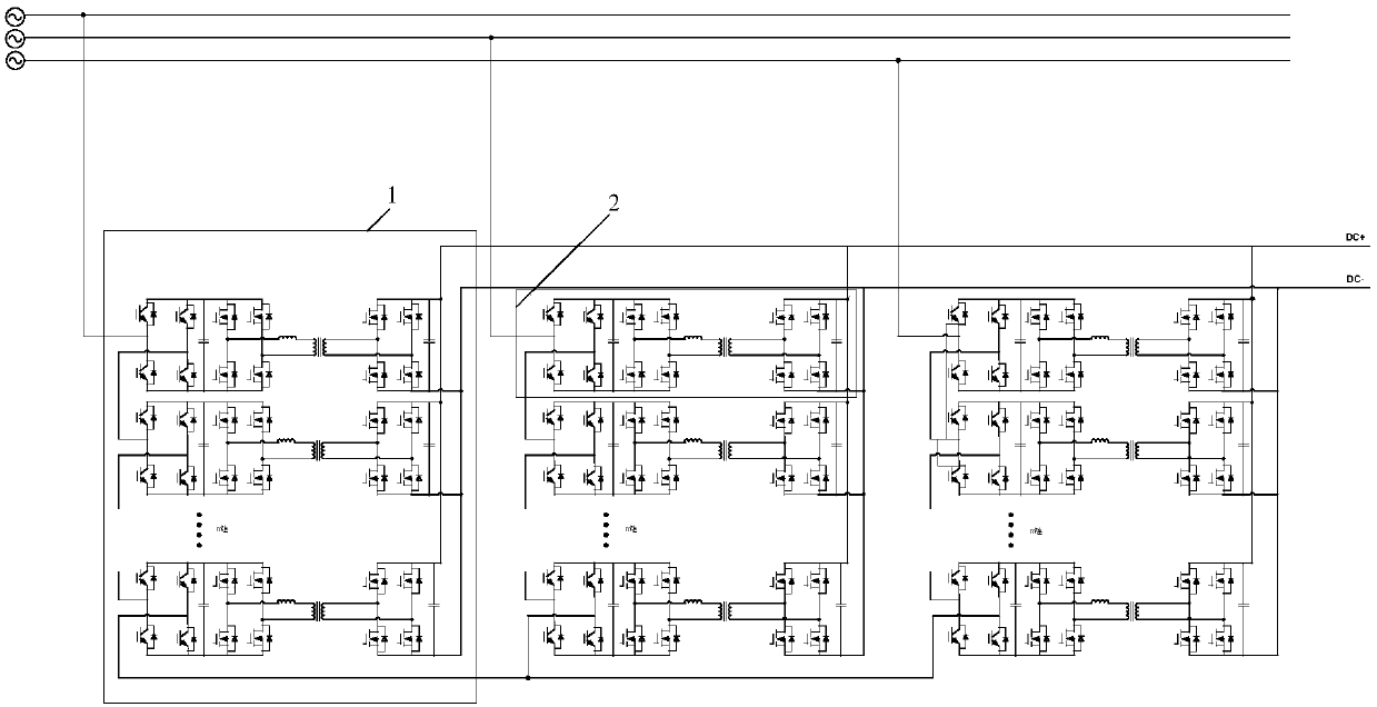
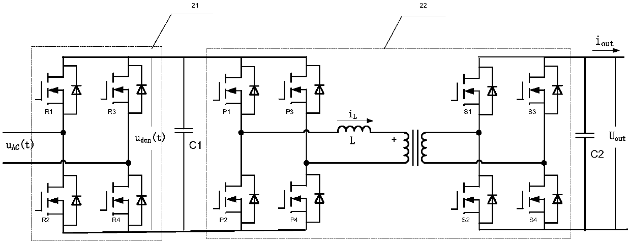
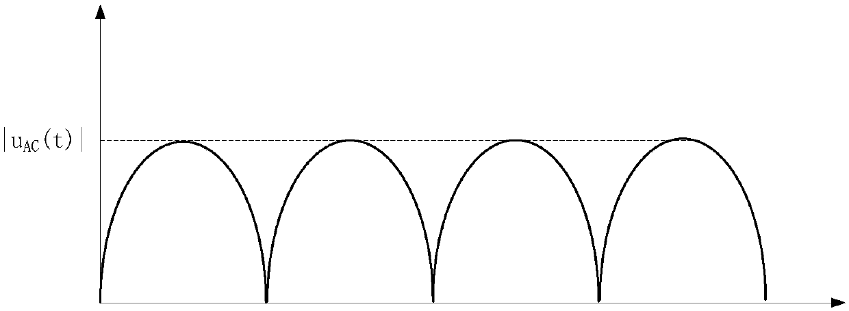
[0048] Since the output voltage Uout of a single module contains 2 times frequency fluctuations, the output voltages of m modules in phase A contain 2 times frequency fluctuations after being connected in parallel, the output voltages of m modules in phase B are connected in parallel contain 2 times frequency fluctuations, and the output voltage of m modules in phase C The parallel connection contains 2 times frequency fluctuations, and the phase difference of the three-phase output voltage is 120°. The three-phase voltages of A, B and C are connected in parallel to offset the 2 times frequency fluctuations. The total output voltage fluctuation of the system is small, so the capacitance values ​​of capacitors C1 and C2 small.


PUM


Abstract

The invention discloses a power electronic transformer system and a control method thereof. The system comprises an A phase interphase transformation module, a B phase interphase transformation moduleand a C phase interphase transformation module and is characterized in that each interphase transformation module comprises a plurality of power conversion modules, an output voltage command value Uout_ref and the actual output voltage Uout subtract Uout_ref/Iout to obtain a load R through a PI adjuster, and the DC bus voltage Udcn(t) of an H-bridge unit is divided by the load R to obtain the input current Iin, the Iin and the Udcn(t) are multiplied to obtain the power P(t), the calculated power P(t) is substituted into a formula to obtain the DAB resonance frequency fs(t). The system reducesDC bus side and output side capacitance, reduces volume and cost, and reduces the control difficulty at the same.

Description

technical field [0001] The invention relates to a power electronic transformer system and a control method thereof, belonging to the technical field of power electronics. Background technique [0002] With the development of power electronics technology, power electronic transformers will replace traditional transformers. At present, power electronic transformers mostly adopt the cascaded form. Each unit module DC bus and DC output side are connected in parallel with filter capacitors to stabilize the voltage and filter out the double frequency voltage. Fluctuation, this form not only increases the volume of the entire system, but also controls the voltage of each capacitor, which increases the difficulty of system control. [0003] The power electronic transformer system and its control method proposed by the present invention reduce the capacitance of the DC bus and the DC output side, and simplify the control difficulty of the whole system while reducing the cost and volu...

Claims


Application Information

Patent Timeline
IPC IPC(8): H02M7/217H02M7/219H02M3/28H02M3/335
CPCH02M3/285H02M3/33576H02M7/2173H02M7/219H02M1/0067H02M1/007
Inventor 黄秋燕邵丹薇杨志李德胜
Owner JIANGSU WANBANG DEHE NEW ENERGY TECH CO LTD
Why Eureka
Try Eureka