Method for operating filtering device

A filter device and operation method technology, applied in the direction of filter separation, separation method, filter circuit, etc., can solve the problems that the filter equipment cannot complete the filter task, is toxic and harmful, and has complex components, and achieves the effect of improving the rapid removal efficiency

Active Publication Date: 2019-04-30
广西桦源环保科技有限公司
View PDF5 Cites 0 Cited by
  • Summary
  • Abstract
  • Description
  • Claims
  • Application Information

AI Technical Summary

Problems solved by technology

High-concentration organic wastewater has the characteristics of high concentration, complex composition, poisonous and harmful, and if it is directly discharged into the water body without treatment, it will seriously pollute the water body environment
[0004] However, after water degradation, it needs to be comprehensively treated according to its characteristics, such as biodegradation and chemical degradation, but these degradation methods cannot meet the existing production speed, and most of them are caused by the inability to control the concentration of harmful substances in wastewater during the degradation process. Most of the existing equipment directly transports wastewater to the degradation tank. Although the direct degradation has a fast wastewater transport speed and does not affect the exhaust gas emission efficiency, the wastewater is prone to exceed the discharge standard; and due to the harmful The substance content is not the same, so that a single filter device cannot complete its filtering task

Method used


Image

  • Method for operating filtering device
  • Method for operating filtering device
  • Method for operating filtering device

Examples


Embodiment 1

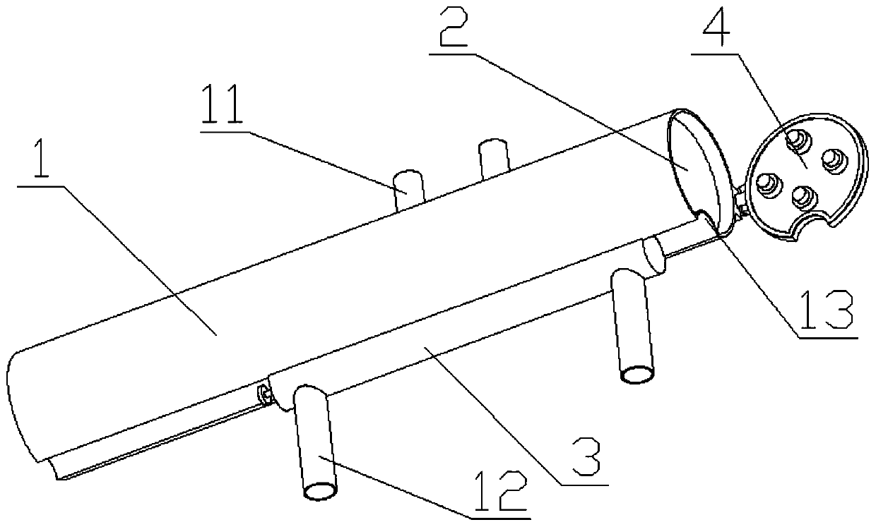
[0039] like Figure 1 to Figure 6Shown; A kind of operation method of filter device, comprises filter pipe 1, filter mechanism 2 and controller, described filter mechanism 2 is arranged in the filter pipe 1, and described filter pipe 1 end is provided with pressure measurement sealing mechanism 4, The other end of the filter tube 1 is provided with an oil cylinder, and the power end of the oil cylinder presses the filter mechanism 2 on the working side of the pressure measuring and sealing mechanism 4; One side of the filter pipe 1 of the liquid pipe 11 is provided with an anti-blocking sewage discharge mechanism 3, the liquid inlet pipe 12 is connected to the anti-blockage sewage discharge mechanism 3, a vacuum water tank is connected to the liquid discharge pipe 11, and a vacuum water tank is arranged on the vacuum water tank. There are vacuum pumps, drains and pressure gauges, the anti-blocking and sewage discharge mechanism 3 communicates with the filter pipe 1 and coopera...

Embodiment 2

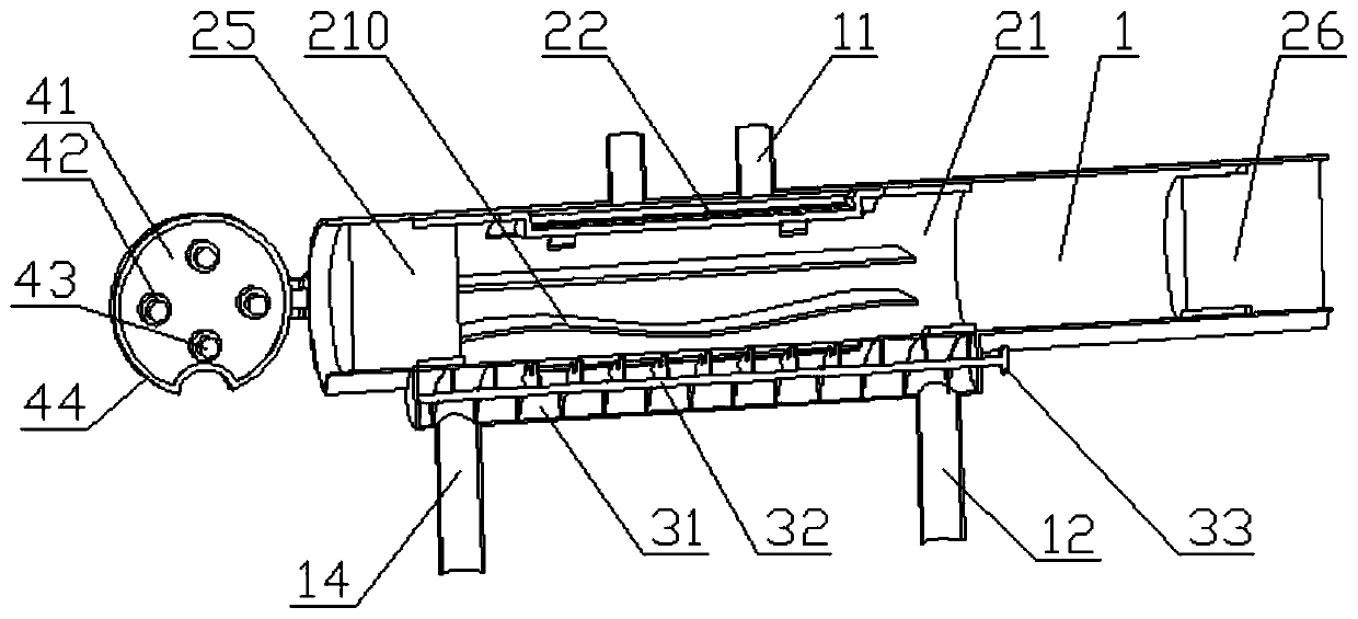
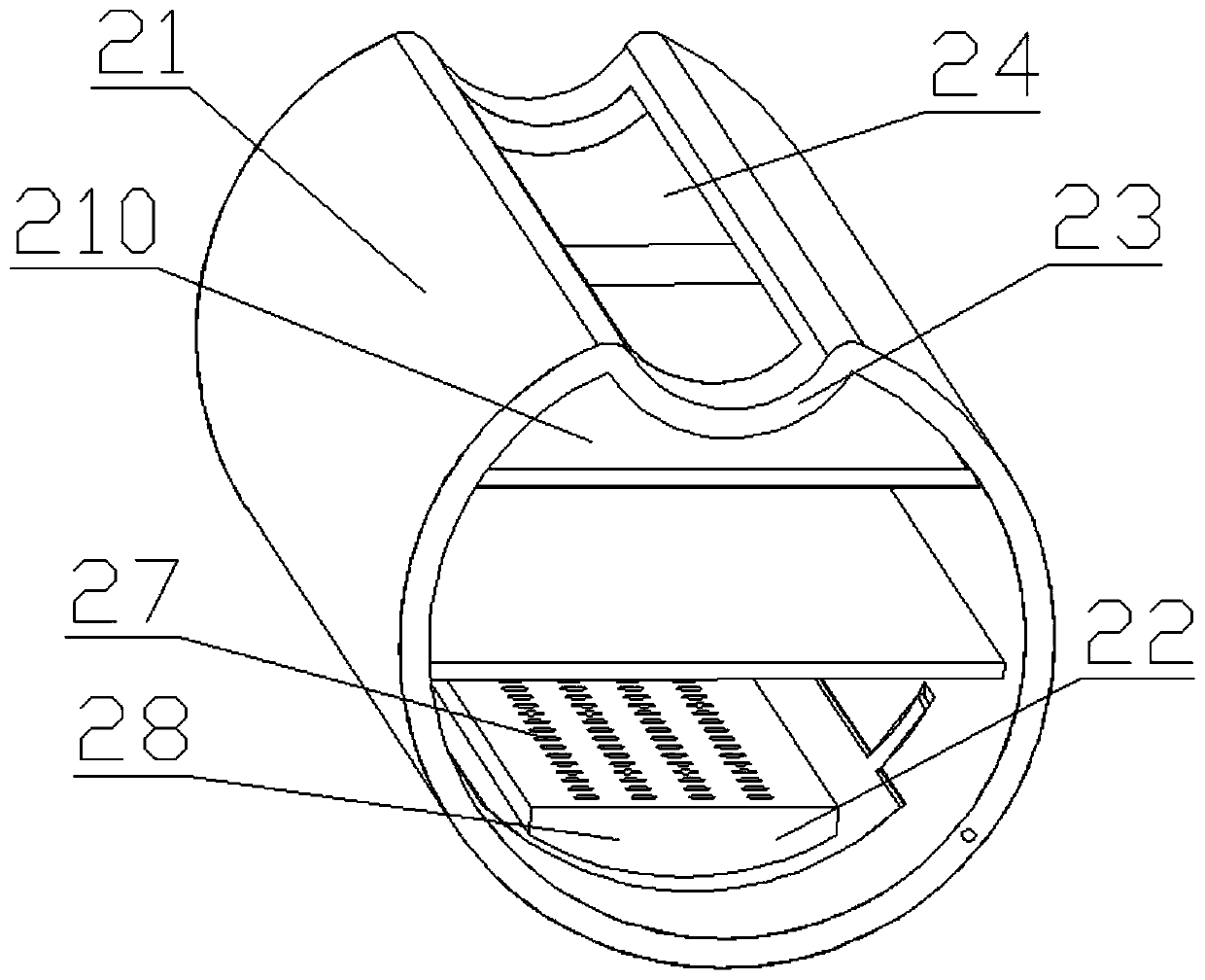
[0056] On the basis of Embodiment 1, the pressure measuring and sealing mechanism 4 includes a sealing door 41, and at least one pressure sensor 42 is arranged on the sealing door 41, and a buffer block 43 is arranged on the pressure sensor 42. The sealing door 41 is provided with a sealing gasket 44; the pressure sensor 42 is electrically connected to the controller; one side of the filter barrel 21 is provided with a filtered liquid door 22, and the filtered liquid door 22 is provided with a concave return cavity 27, the liquid outlet hole 28 is set on the concave return cavity 27; the filter barrel 21 is provided with an inner arc-shaped sliding wall 23 on one side, the transition hole 24 is set in the inner arc-shaped sliding wall 23, and the filter One side of the tube 1 is provided with an outer arc-shaped sliding wall 13 that cooperates with the inner arc-shaped sliding wall 23; the filter bucket 21 is provided with at least two sealing strips, and the sealing strips are...

Embodiment 3

[0059] On the basis of Example 2, the gap between the filter tube 1 and the filter bucket 21 is 0.5mm to 2.0mm, and the thickness of the sealing ring 29 is 10mm to 20mm; the sealing ring 29 is made of silica gel, and the silica gel The hardness is 20 degrees to 50 degrees; the screw 32 revolving blade located on one side of the transition hole 24 is provided with a slow pressure cleaning notch 34; the ratio of the width of the screw 32 revolving blade to the width of the slow pressure cleaning notch 34 1:0.3~0.7.

[0060]By setting the gap between the filter tube 1 and the filter bucket 21 to 0.5mm to 2.0mm, the phenomenon of difficulty in installation can be avoided. If the gap is too large, the filter will also flow directly to the liquid outlet pipe 11; It is set to 10mm to 20mm, and the hardness is set to 20 degrees to 50 degrees, so that after the sealing ring 29 is under pressure, one side thereof will be squeezed and deformed so that the side surface contacts the inner ...


PUM

PropertyMeasurementUnit
thicknessaaaaaaaaaa
hardnessaaaaaaaaaa

Abstract

The invention discloses a method for operating filtering device. The filtering device comprises a filter tube, a filtering mechanism and a controller, the filtering mechanism is arranged in the filtertube, a pressure-measuring sealing mechanism is arranged at one end of the filter tube, an oil cylinder is arranged at the other end of the filter tube, and the power end of the oil cylinder pressesthe filtering mechanism to the working side of the pressure-measuring sealing mechanism; one side of the filter tube is connected with a liquid outlet tube, an anti-blocking dirt discharging mechanismis arranged at one side, away from the liquid outlet tube, of the filter tube, the anti-blocking dirt discharging mechanism is connected with a liquid inlet tube, a vacuum water tank is provided witha vacuum pump, a water discharging port and a pressure gauge, and the anti-blocking dirt discharging mechanism is communicated with the filter tube and cooperates with the filtering device. The method for operating filtering device generates a negative pressure by the vacuum pump to make wastewater quickly pass through the filtering mechanism, so the rapid removal efficiency of particulate matters in the wastewater is increased, thereby the filtration speed is increased, and the wastewater recycling rate is increased.

Description

technical field [0001] The invention belongs to the field of filtering devices, and in particular relates to an operating method of the filtering device. Background technique [0002] At present, there are three main sources of air pollution: Industry: Industry is an important source of air pollution. The pollutants discharged into the atmosphere by industry are various and complex in nature, including smoke, sulfur oxides, nitrogen oxides, organic compounds, Halides, carbon compounds, etc., some of which are smoke and some are gases; domestic stoves and heating boilers: a large number of civilian stoves and heating boilers in cities need to consume a lot of coal, and coal will release a lot of dust, sulfur dioxide, carbon dioxide, and carbon monoxide during combustion Such harmful substances pollute the atmosphere, especially when heating in winter, often make the polluted area filled with smog and make people cough, which is also a source of pollution that cannot be ignore...

Claims


Application Information

Patent Timeline
Patent Type & Authority Applications(China)
IPC IPC(8): B01D36/02
CPCB01D36/02
Inventor 不公告发明人
Owner 广西桦源环保科技有限公司
Why Eureka
Try Eureka