Resonant gate driving circuit suitable for high-frequency application

A gate drive, resonant inductor technology, applied in the direction of high-efficiency power electronic conversion, electrical components, output power conversion devices, etc., can solve the problem of increasing the gate drive loss, affecting the drive pulse performance, slowing the turn-on speed and turn-off speed. and other problems, to achieve the effect of improving the driving performance, optimizing the gate driving voltage waveform, and reducing the loss of the driving loop

Inactive Publication Date: 2019-04-30
SOUTHEAST UNIV +1
View PDF2 Cites 11 Cited by
  • Summary
  • Abstract
  • Description
  • Claims
  • Application Information

AI Technical Summary

Problems solved by technology

[0003] At present, many companies such as CREE and Rohm have designed drive circuits suitable for high-frequency applications. The most used drive circuit structure is to add the push-pull output stage of the drive to the gate of the power switch tube through a gate resistor Rg. pole, or use different drive resistance Ron and turn-off resistance Roff at the gate, which not only slows down the turn-on speed and turn-off speed of the gate of the switch, but also increases the gate drive loss, and the gate stray The presence of inductance will also affect the performance of the drive pulse

Method used


Image

  • Resonant gate driving circuit suitable for high-frequency application
  • Resonant gate driving circuit suitable for high-frequency application
  • Resonant gate driving circuit suitable for high-frequency application

Examples


Embodiment Construction

[0038] The technical solutions of the present invention will be further described below in conjunction with the accompanying drawings and specific embodiments.

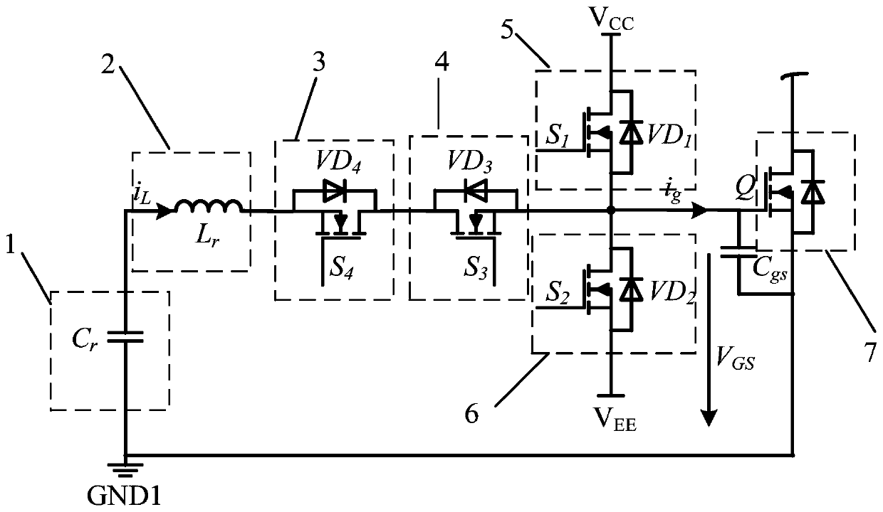
[0039] Such as figure 1 As shown, a resonant gate drive circuit suitable for high-frequency applications includes resonant capacitor Cr1, resonant inductor Lr2, auxiliary switch tube 1 3, auxiliary switch tube 2 4, main switch tube 1 5, main switch tube 2 6 and Main power device Q 1 7;

[0040] The resonant capacitor Cr1 is connected in series with the resonant inductance Lr2, the resonant inductance Lr2 is connected to the source of the auxiliary switch tube one 3, the drain of the auxiliary switch tube one 3 is connected to the drain of the auxiliary switch tube two 4, and the auxiliary switch tube two 4 The source and the source of the main switching tube 1, the drain of the main switching tube 2 6 and the main power device Q 1 The gate of 7 is connected, and the drain of the main switching tube 5 is connected t...


PUM


Abstract

The invention discloses a resonant gate driving circuit suitable for a high-frequency application. The resonant gate driving circuit comprises a resonant capacitor Cr, a resonant inductor Lr, an auxiliary switching tube 1, an auxiliary switching tube 2, a main switching tube 1, a main switching tube 2 and a main power device Q1. The resonant capacitor Cr is connected in series with the resonant inductor Lr, the resonant inductor Lr is connected to a source electrode of the auxiliary switching tube 1, a drain electrode of the auxiliary switching tube 1 is connected to a drain electrode of the auxiliary switching tube 2, a source electrode of the auxiliary switching tube 2 is connected to a source electrode of the main switching tube 1, a drain electrode of the main switching tube 2 and a gate of the main power device Q1, a drain electrode of the main switching tube 1 is connected to a positive power supply voltage VCC, and a source electrode of the main switching tube 2 is connected tonegative power supply voltage VEE. According to the driving circuit of the invention, the resonant capacitor Cr, the resonant inductor Lr and the four switching tubes S1, S2, S3 and S4 are used to achieve gate resonant driving, the driving circuit can recover gate driving power, the driving circuit loss is reduced, and the switch-on and switch-off times of the main power device are shortened.

Description

technical field [0001] The invention belongs to the field of circuit driving, and in particular relates to a resonant gate driving circuit topology design suitable for high-frequency applications. Background technique [0002] With the development of power electronic devices, more and more people pay attention to wide bandgap semiconductor devices, and power electronic devices are developing towards high frequency and integration. At present, the switching frequency of power electronic devices can reach more than MHz, which brings great challenges to the design of high-frequency drive circuits. Reducing the parasitic parameters of the drive circuit and reducing the loss of the drive circuit has become a research hotspot. [0003] At present, many companies such as CREE and Rohm have designed drive circuits suitable for high-frequency applications. The most used drive circuit structure is to add the push-pull output stage of the drive to the gate of the power switch tube thr...

Claims


Application Information

Patent Timeline
Patent Type & Authority Applications(China)
IPC IPC(8): H02M1/08
CPCH02M1/083H02M1/0058Y02B70/10
Inventor 张建忠吴海富朱耀东赵进
Owner SOUTHEAST UNIV
Why Eureka
Try Eureka