Permanent magnet synchronous motor control method, device and electronic equipment

A technology of permanent magnet synchronous motor and control method, which is applied in the direction of motor generator control, electromechanical transmission control, electronic commutation motor control, etc., and can solve problems such as easy out-of-step and motor out-of-step

Active Publication Date: 2020-07-07
ZHENGZHOU UNIVERSITY OF LIGHT INDUSTRY
View PDF1 Cites 0 Cited by
  • Summary
  • Abstract
  • Description
  • Claims
  • Application Information

AI Technical Summary

Problems solved by technology

However, the motor is prone to out-of-step when switching from the high-frequency signal injection method in the low-speed stage to the sliding mode observer control in the medium-high speed stage.
[0004] To sum up, the control method of the permanent magnet synchronous motor in the prior art has the technical problem that the process of switching from low-speed control to high-speed control is prone to out-of-step

Method used


Image

  • Permanent magnet synchronous motor control method, device and electronic equipment
  • Permanent magnet synchronous motor control method, device and electronic equipment
  • Permanent magnet synchronous motor control method, device and electronic equipment

Examples


Embodiment 1

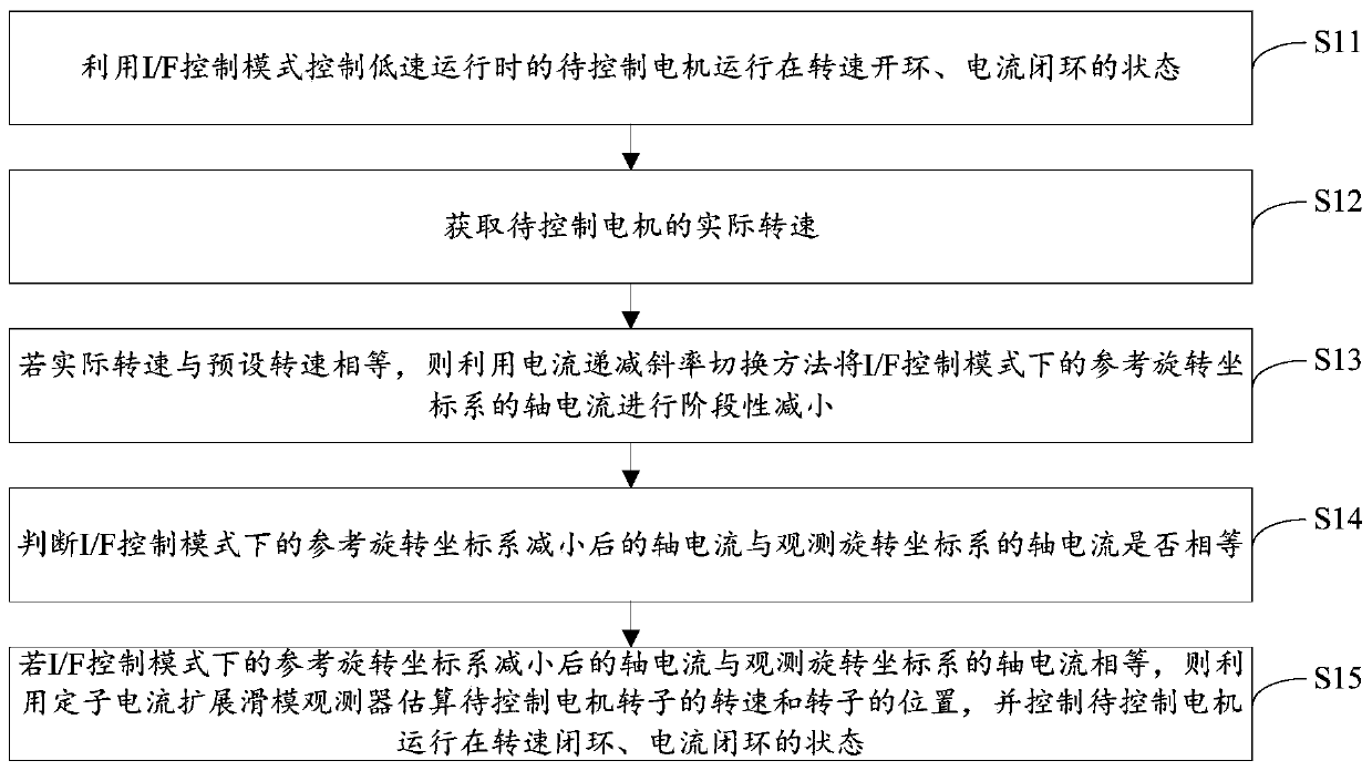
[0031] figure 1 is a permanent magnet synchronous motor control method according to an embodiment of the present invention, such as figure 1 As shown, the method includes the following steps:

[0032] Step S11, using the I / F control mode to control the motor to be controlled during low-speed operation to run in the state of speed open loop and current closed loop;

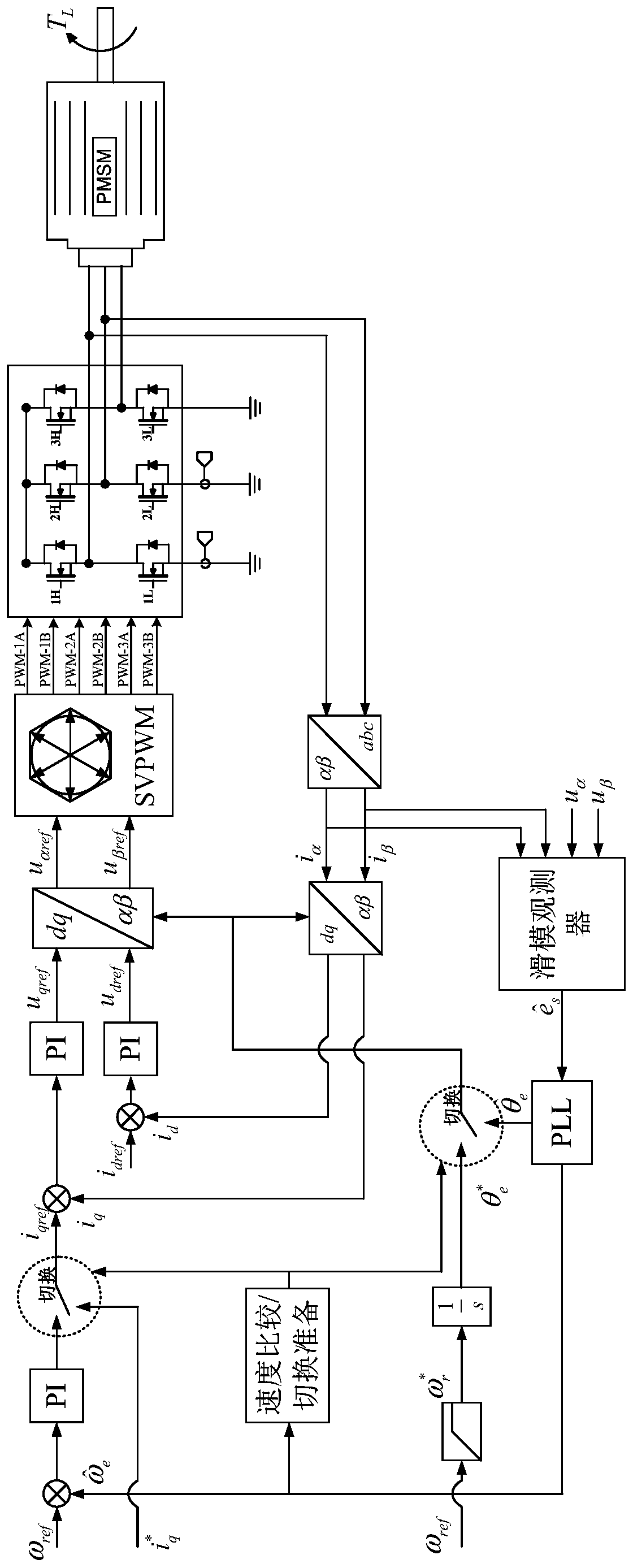
[0033] Please refer to the control block diagram of the inventive method figure 2 , when the motor to be controlled is running at low speed, the I / F control mode is adopted to make the motor to be controlled run in the state of open-loop speed and closed-loop current. The specific content of the I / F control mode will be introduced in detail below.

[0034] Step S12, obtaining the actual rotational speed of the motor to be controlled;

[0035]The starting process of the motor to be controlled should be a smooth acceleration process. When the actual speed of the motor reaches the preset speed, it is necessary to ...

Embodiment 2

[0095] The embodiment of the present invention also provides a permanent magnet synchronous motor control device, the permanent magnet synchronous motor control device is mainly used to implement the permanent magnet synchronous motor control method provided by the above content of the embodiment of the present invention, the following provides the embodiment of the present invention The permanent magnet synchronous motor control device is introduced in detail.

[0096] Figure 14 is a schematic diagram of a permanent magnet synchronous motor control device according to an embodiment of the present invention, such as Figure 14 As shown, the permanent magnet synchronous motor control device mainly includes: a low-speed control module 10, an acquisition module 20, a calculation module 30, a comparison module 40, and a high-speed control module 50, wherein:

[0097] The low-speed control module 10 uses the I / F control mode to control the motor to be controlled during low-speed ...

Embodiment 3

[0109] An embodiment of the present invention provides an electronic device, referring to Figure 15 , the electronic device includes: a processor 60, a memory 61, a bus 62 and a communication interface 63, the processor 60, the communication interface 63 and the memory 61 are connected through the bus 62; the processor 60 is used to execute the executable stored in the memory 61 Modules, such as computer programs.

[0110] Wherein, the memory 61 may include a high-speed random access memory (RAM, Random Access Memory), and may also include a non-volatile memory (non-volatile memory), such as at least one disk memory. The communication connection between the system network element and at least one other network element is realized through at least one communication interface 63 (which may be wired or wireless), and the Internet, wide area network, local network, metropolitan area network, etc. can be used.

[0111] The bus 62 can be an ISA bus, a PCI bus or an EISA bus, etc. ...


PUM


Abstract

The invention provides a control method and device for a permanent magnet synchronous motor, and electronic equipment, and relates to the technical field of permanent magnet synchronous motors. The method comprises the following steps: controlling a to-be-controlled motor in low-speed operation by utilizing an I / F control mode; if the actual rotating speed of the to-be-controlled motor is equal tothe preset rotating speed, performing staged reduction of a q*axis current of a reference rotating coordinate system in the I / F control mode by using a current decreasing slope switching method; estimating a rotating speed and the position of the motor rotor to be controlled by using a stator current expansion sliding mode observer if the q*axis current obtained after reduction is equal to an axis current (shown in the description) of an observation rotating coordinate system, and controlling the motor to be controlled to operate in a rotating speed closed-loop state and a current closed-loopstate. According to the invention, the p method provided by the invention can achieve the stable switching of the control mode when the q*axis current of the reference rotating coordinate system is equal to the axis current of the observation rotating coordinate system, and solves the technical problem that in the prior art, the process from low-speed control to high-speed control switching of the control method of the permanent magnet synchronous motor is prone to step out is solved.

Description

technical field [0001] The invention relates to the technical field of permanent magnet synchronous motors, in particular to a control method, device and electronic equipment for permanent magnet synchronous motors. Background technique [0002] Permanent magnet synchronous motors have been widely used in the fields of fans, pumps and electric vehicles due to their high power density and wide speed range. In order to realize the efficient vector control of permanent magnet synchronous motor, it is necessary to obtain the position and speed information of the motor rotor in real time. In recent years, scholars at home and abroad have conducted in-depth research on the position sensorless control technology of permanent magnet synchronous motors. The position sensorless control technology is conducive to improving the reliability of permanent magnet synchronous motor drive systems, simplifying the system structure, and reducing operating environment requirements. . [0003] ...

Claims


Application Information

Patent Timeline
Patent Type & Authority Patents(China)
IPC IPC(8): H02P21/00H02P21/13
Inventor 申永鹏刘安康杨存祥邱洪波葛高瑞杨小亮武洁郑竹风
Owner ZHENGZHOU UNIVERSITY OF LIGHT INDUSTRY
Why Eureka
Try Eureka