
Multi-section spiral continuous feeding device for particle materials

A kind of feeding device, technology of granular material

Active Publication Date: 2019-05-07
BEIJING UNIV OF CHEM TECH
View PDF8 Cites 9 Cited by
  • Summary
  • Abstract
  • Description
  • Claims
  • Application Information

AI Technical Summary

Problems solved by technology

For rubber and plastics, the fixed-diameter screw conveyor is not easy to form a plug seal, while the variable-diameter and variable-pitch screw conveyor is easy to cause sticky materials, and the feeding speed is uneven, and the feeding speed cannot be accurately controlled, which is easy to cause feeding. Silo full or short of material

Method used


Image

  • Multi-section spiral continuous feeding device for particle materials
  • Multi-section spiral continuous feeding device for particle materials
  • Multi-section spiral continuous feeding device for particle materials

Examples


Embodiment 1

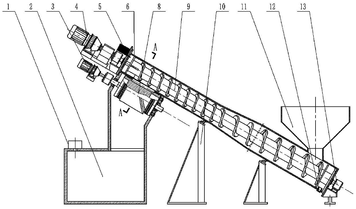
[0022] Waste tire rubber granules are an embodiment of the present invention. Waste tire rubber granules enter the screw conveying device from the feed port (11) (13), and use the propulsion of the screw blade to make the raw material form a material plug during operation to achieve material self-sealing. , the material enters between the tooth grooves of the feed gear (8), falls evenly into the feed bin (21) as the feed gear (8) rotates, and falls into the reactor (2).

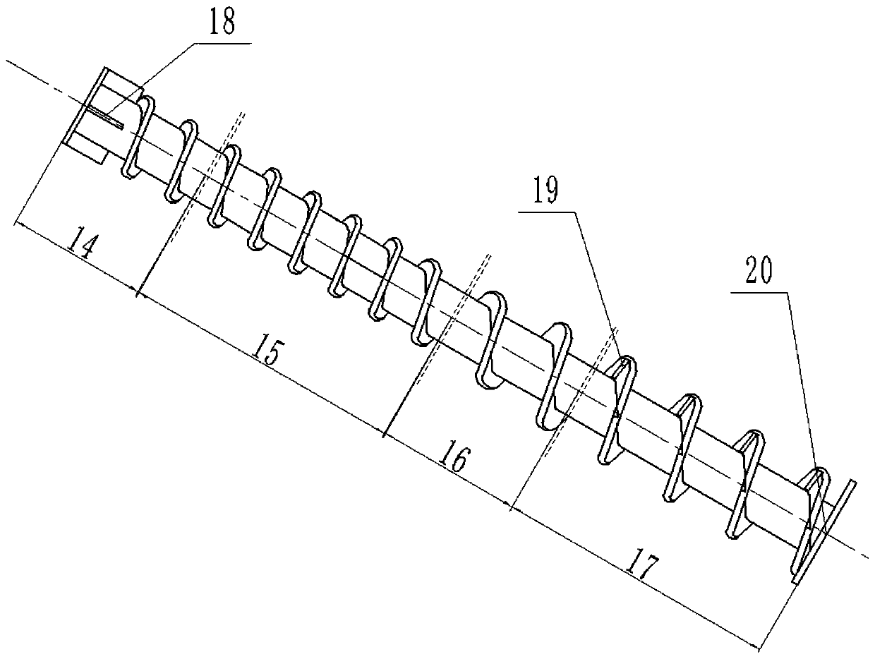
[0023] First turn on the motor, the screw conveying device and the feed gear (8) are running and do not open the reactor temporarily, the feed port (11) is filled with materials, and the materials are compressed through the variable diameter extrusion section (16), and are conveyed in the small diameter and small pitch conveying section ( 15) The inside is compacted, the material moves to the discharge port (24), the feed gear (8) scrapes the material into the tooth groove and takes it out of the screw conveyo...

Embodiment 2

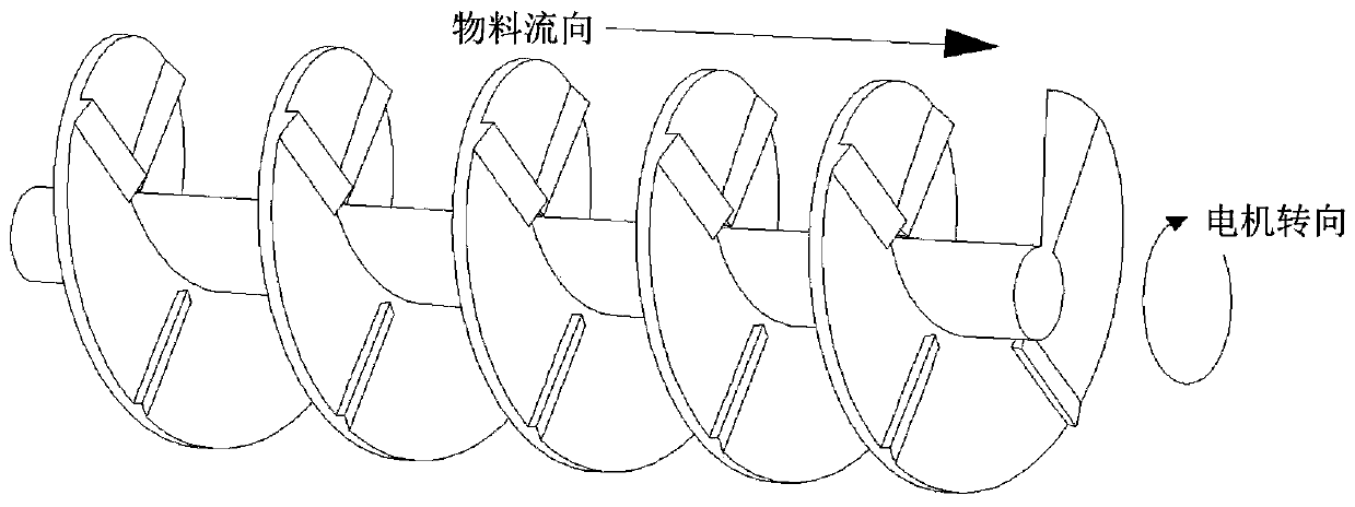
[0027] In another technical scheme, the feed gear (8) is a left-handed gear (28), such as Figure 5b , Figure 6b As shown, when the feed gear (8) and the screw conveyor (9) rotate in opposite directions, the material flow direction near the discharge port (24) is the same as the gear tooth movement direction, and when the feed gear (8) and the screw conveyor (9) Rotate in the same direction, the direction of material flow near the discharge port (24) is opposite to the direction of gear tooth movement, but because the inclined direction of gear teeth is opposite to the direction of material flow, the scraping effect is weak, which is suitable for strong fluidity , Materials with poor toughness, such as PVC.

Embodiment 3

[0029] In another technical scheme, the feed gear (8) is a spur gear (29), such as Figure 5c , Figure 6c Shown, feeding gear (8) and screw conveyor (9) rotation direction all have scraping effect preferably, but scope of application is not as good as right-handed gear (27), is not as good as left-handed gear to harder material.


PUM


Abstract

The invention discloses a multi-section spiral continuous feeding device for particle materials. The multi-section spiral continuous feeding device for the particle materials comprises a spiral conveying device and a gear feeding device; the spiral conveying device comprises a machine cylinder, a feeding port, a discharging port, a spiral conveyor, an upper motor, a material scraper plate, a material baffle, a spraying port, a dust outlet and a support; and the gear feeding device comprises a material bin, a feeding gear, a material leakage blocking groove, a flange disc, a mechanical seal anda bearing. The materials can be compacted into a material plug in a reducing variable-pitch spiral mode, and self-sealing of the materials is formed; and the material plug can be smashed through thegear feeding device, and then the materials can be uniformly, accurately and efficiently fed. According to the multi-section spiral sealing feeding device for the particle materials, the materials canbe continuously fed into a sealed continuous cracking reactor, and the purposes that safe production is achieved, continuous feeding is achieved, the production efficiency is improved, and energy sources are saved are achieved.

Description

technical field [0001] The invention relates to screw feeding equipment in the field of chemical industry, in particular to a multi-segment screw continuous feeding machine with sealing function. Background technique [0002] In recent years, there are mainly two types of rubber and plastic processing and production equipment: intermittent and continuous. Intermittent equipment is gradually being eliminated by continuous equipment because of its cumbersome operation and low production efficiency. Continuous equipment needs to maintain a vacuum environment inside the equipment during the reaction process, so continuous feeding equipment with sealing function has been widely used in recent years. There are mainly three types of continuous feeding equipment with sealing function: first, multi-level silo feeding, multi-level silo feeding usually has a transition silo, from the first-level silo to the transition silo, and then Feed from the transitional silo to the pyrolysis equ...

Claims


Application Information

Patent Timeline
Patent Type & Authority Applications(China)
IPC IPC(8): B65G65/46B65G33/26B65G33/34B01J4/00
Inventor 张冰付琦耿煜董浩王永强
Owner BEIJING UNIV OF CHEM TECH
Learn More