Voltage regulating circuit and inverter system

A technology of voltage regulation circuit and circuit switch, applied in the field of power electronics, can solve the problems of small thermal stress, large open circuit voltage and large thermal stress of semiconductor devices, and achieve the effect of reducing peak voltage and reducing heat loss

Active Publication Date: 2019-05-07
HUAWEI DIGITAL POWER TECH CO LTD
View PDF3 Cites 2 Cited by
  • Summary
  • Abstract
  • Description
  • Claims
  • Application Information

AI Technical Summary

Problems solved by technology

like figure 2 As shown, the current photovoltaic power generation system has the characteristics of large open circuit voltage and low current, low full-load output voltage and large current, which leads to the control of semiconductor devices such as switches used in inverters and other circuits under the condition of large voltage stress. Small thermal stress, large thermal stress at low voltage stress
In addition, in order to increase the power density of the battery panel, the open circuit voltage of the photovoltaic power generation system has been continuously increased in recent years, which has led to the continuous increase of the input voltage of the inverter, and the voltage stress on the semiconductor device is increasing, which affects the performance of the semiconductor device. The requirements are becoming more and more stringent, and the selectivity of semiconduc

Method used


Image

  • Voltage regulating circuit and inverter system
  • Voltage regulating circuit and inverter system
  • Voltage regulating circuit and inverter system

Examples


Embodiment Construction

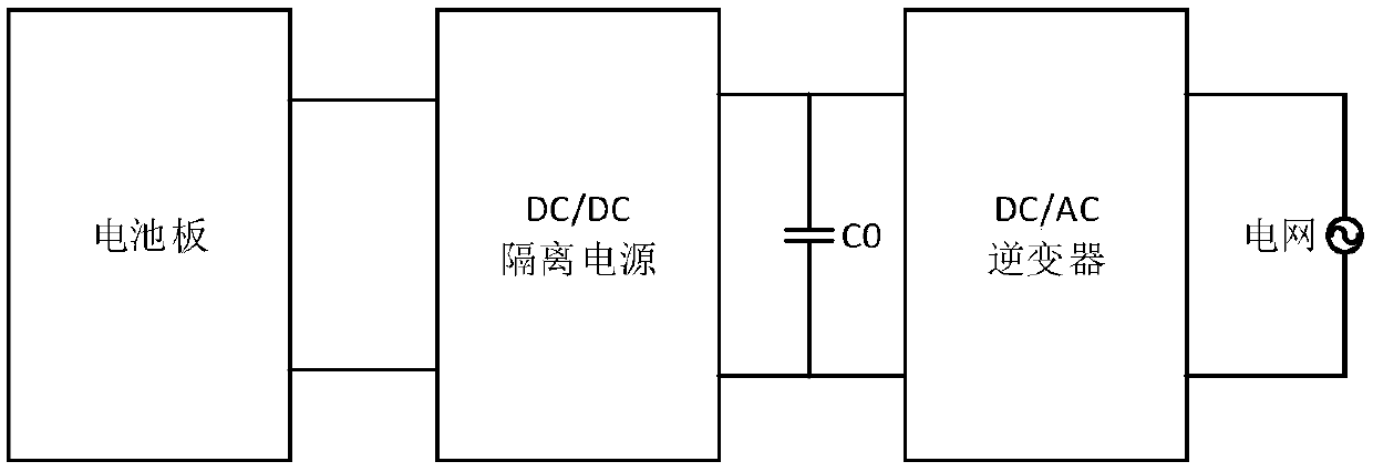
[0030] Before describing the technical solution of the embodiment of the present application, the technical scene of the embodiment of the present application will be described first with reference to the accompanying drawings.

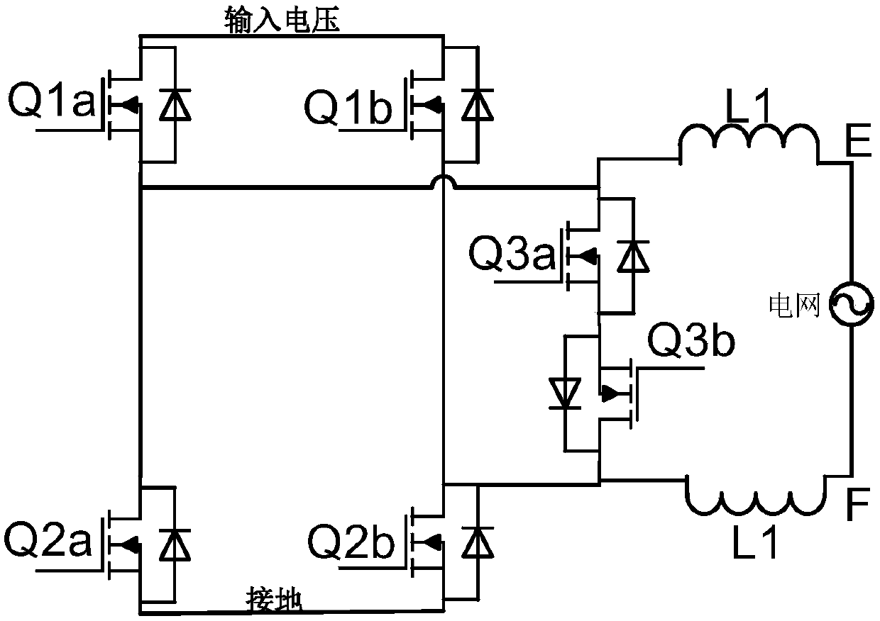
[0031] see image 3 , is a schematic structural diagram of a DC / AC inverter. At present, in the photovoltaic power generation system, the mainstream DC / AC inverter structure is image 3 The H6 bridge topology is shown. The main circuit of this structure is composed of 6 switch tubes connected in parallel with diodes. The switch tubes in the main circuit are provided with the bus voltage by the bus capacitor of the DC / DC isolated power supply, and control the switch by driving the optocoupler The closing and opening of the tube realizes the high-frequency sinusoidal pulse width modulation (sinusoidal pulse width modulation, SPWM) of the switch tube, and modulates the direct current from the isolated power supply into alternating current, and outputs i...


PUM


Abstract

The application provides a voltage regulating circuit and an inverter system. The voltage regulating circuit includes a first voltage-regulator tube, a second voltage-regulator tube, a voltage stabilizing resistor, a circuit switch, a first capacitor and a second capacitor, wherein the first voltage-regulator tube and the first capacitor are connected in parallel between a first node and a secondnode; the voltage stabilizing resistor and the second capacitor are connected in parallel between the second node and a third node; the second voltage-regulator tube and the circuit switch are connected in series between the first node and the second node; the voltage regulation value of the first voltage-regulator tube is different from the voltage regulation value of the second voltage-regulatortube; and the voltage between the first node and the third node is the bus voltage. The voltage regulating circuit provided by the present application can be applied to a photovoltaic power generation system, and the driving voltage of an inverter switching tube can be adjusted through the voltage regulating circuit. Specifically, when the inverter is started, the inverter switching tube is provided with a low driving voltage such that the peak voltage of the switching tube is reduced. A high driving voltage is provided for the switching tube during the high-power operation of the power generation system, thereby reducing heat loss.

Description

technical field [0001] The present application relates to the technical field of power electronics, in particular to a voltage regulating circuit and an inverter system. Background technique [0002] MOSFET and IGBT are currently mainstream controlled switching devices controlled by voltage, and are widely used in photovoltaic power generation systems. figure 1 A structural diagram of the current photovoltaic power generation system, such as figure 1 As shown, in the photovoltaic power generation system, the electric energy generated by the battery panel is transferred to the bus capacitor C0 through the conversion of the DC / DC isolated power supply, and then converted into alternating current by the DC / AC inverter and sent to the grid. A plurality of switching devices and parasitic inductances form a topology structure, and the conversion from direct current to alternating current is realized by controlling the switching states of the switching devices. [0003] figure ...

Claims


Application Information

Patent Timeline
IPC IPC(8): H02M7/48H02J3/38
Inventor 师涛石鹏姚晓锋
Owner HUAWEI DIGITAL POWER TECH CO LTD
Why Eureka
Try Eureka