
Production process method for machine-made sand aggregate

A production process and sand aggregate technology, applied in the field of machine-made sand aggregate production process, to achieve the effects of reliable sealing, moderate water volume and large output

Active Publication Date: 2019-05-10
泰安鲁珠保温建材有限公司
View PDF7 Cites 7 Cited by
  • Summary
  • Abstract
  • Description
  • Claims
  • Application Information

AI Technical Summary

Problems solved by technology

[0005] The technical task of the present invention is to provide a production process for machine-made sand aggregates to solve the problem of how to remove clay impurities and improve the quality of sand aggregates

Method used


Image

  • Production process method for machine-made sand aggregate
  • Production process method for machine-made sand aggregate
  • Production process method for machine-made sand aggregate

Examples


Embodiment 1

[0039] as attached figure 2 Shown, machine-made sand aggregate production process method of the present invention, the method steps are as follows:

[0040] S1. Transport the raw materials to the V-type powder separator for powder selection to obtain pretreated raw materials; the powder selection process of the V-type powder separator is as follows:

[0041] S101, V-type powder classifier The position of the outlet of the lower body of the powder separator is equipped with a grinding and shaping device. The grinding and shaping device includes a movable shaft, a rubbing block and a rubbing ring, and the rubbing block and the rubbing ring are installed through the movable shaft. The relative extrusion movement between them realizes rubbing and shaping the materials passing through the outlet of the lower body, and produces a retreat buffer for the passing materials to prevent excessive wear of materials and equipment damage caused by forced extrusion;

[0042] S102. The size ...

Embodiment 2

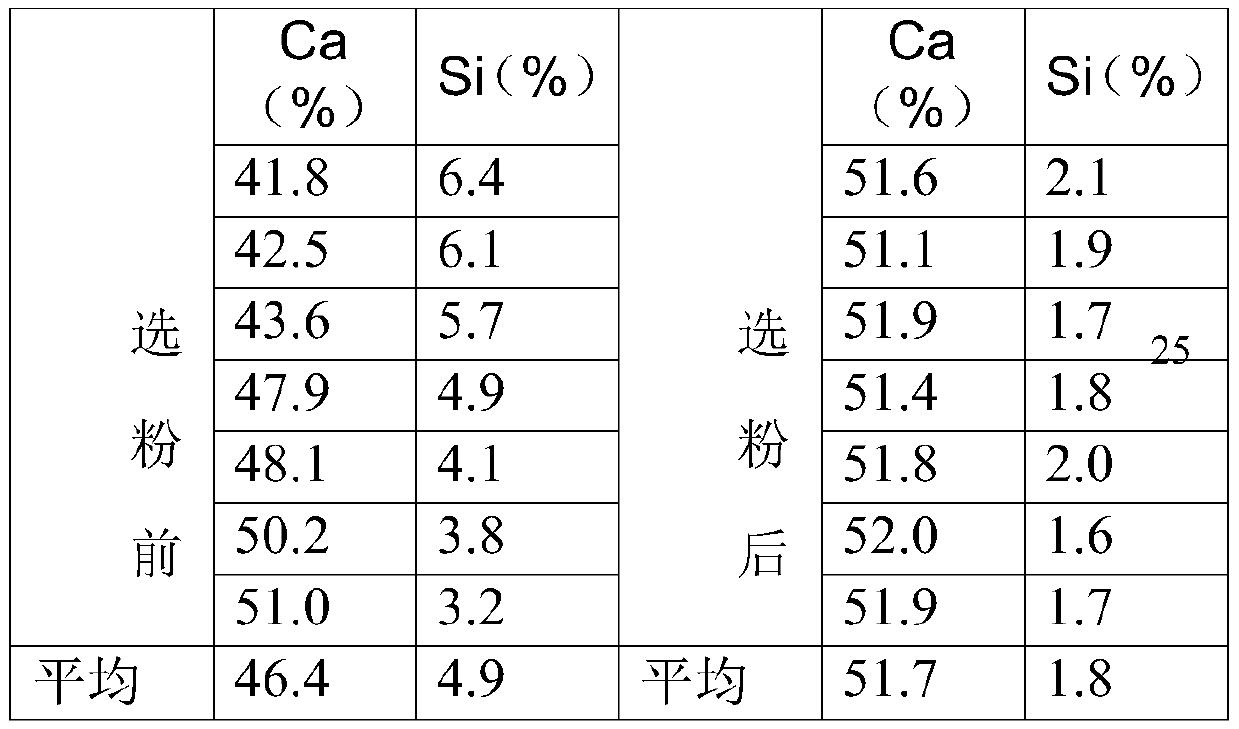
[0053] The quality of limestone raw materials determines the quality of machine-made sand, especially when the clay content is high, resulting in increased water demand for concrete and mortar, large plastic shrinkage, and cracking of components. After the limestone mixture is selected by the V-type powder classifier, the quality has been greatly improved and stabilized after repeated tests and comparisons.

[0054] Comparison of Ca (limestone) and Si (clay) content before and after powder selection:

[0055]

[0056] It can be seen from the table that after the powder selection process, the clay content of the product is significantly reduced, which not only increases the output of the machine-made sand aggregate, but also improves the quality of the machine-made sand aggregate.

[0057] In addition, the machine-made sand produced by the traditional process is not good in shape, with sharp edges and corners, rough surface, too many needles and flakes, a large fineness modu...


PUM


Abstract

The invention discloses a production process method for machine-made sand aggregate and belongs to the field of sand aggregate production. The production process method solves the technical problem ofhow to remove clay impurities and improve the quality of the sand aggregate. According to the technical scheme, the method comprises the following steps: S1, conveying a raw material to a V-shaped powder concentrator to concentrate powder to obtain pre-treated raw material; S2, dedusting the pre-treated raw material by a bag type dust collector I while concentrating powder; S3, conveying the pre-treated raw material to a crusher to be crushed through a lifter to obtain a crushed material; S4, conveying the crushed material to an analogue-digital control screen to be screened to obtain a screened material; S5, dedusting the screened material through a bag type dust collector II while screening the material by the analogue-digital control screen; S6, conveying the screened material to a particle shape optimizing machine to granulate to obtain an optimized grain sand aggregate; and S7, conveying the optimized grain sand aggregate which is humidified by a humidifying stirrer to a belt conveyor.

Description

technical field [0001] The invention relates to the field of sand aggregate production, in particular to a production process for machine-made sand aggregate. Background technique [0002] In developing countries, the sand and gravel aggregate industry has entered a period of rapid development after experiencing a period of "extensive" development. Due to the relatively backward infrastructure, large market capacity, many new infrastructure projects, and the increasing consumption of sand and gravel aggregates, many experts and industry insiders at home and abroad are very optimistic about the future of my country's sand and gravel aggregate industry. [0003] Sand and gravel is an industry attached to natural quarry resources. In the past few decades, it has been traditionally extensive mining, and in recent years it has gradually turned into industrialized large-scale production. In 2013, there were more than 28,000 sand and gravel aggregate enterprises above designated s...

Claims


Application Information

Patent Timeline
IPC IPC(8): B02C23/08C04B20/02C04B14/28
Inventor 赵建国
Owner 泰安鲁珠保温建材有限公司
Learn More