Integrated electronic hydraulic braking system and method

A hydraulic braking, integrated technology, applied in the direction of brakes, brake components, brake transmission devices, etc., can solve the problems of high-pressure accumulator leakage, the impact of system braking efficiency, increase the difficulty of system control, etc., to ensure The effect of normal braking, improved active safety performance, improved safety and reliability

Inactive Publication Date: 2019-05-10
JIANGSU UNIV
View PDF6 Cites 7 Cited by
  • Summary
  • Abstract
  • Description
  • Claims
  • Application Information

AI Technical Summary

Problems solved by technology

[0004] The electronic hydraulic brake disclosed in the Chinese Patent Application No. 201310272676.1, Publication No. CN103318158A, and titled "Automotive Integrated Electronic Hydraulic Brake System" uses a motor to drive a hydraulic pump to store high-pressure oil in a high-pressure energy storage system. However, the structure of the system is too complicated, and the high-pressure accumulator may leak, which will affect the braking performance of the system
[0005] The Chinese patent application number is 201710261316.X, the publication number is CN107031597A, and the system disclosed in the document titled "An Integrated Electro-hydraulic Braking System and Method" adopts the combination of worm gear and rack and pinion as the structure. The transmission mechanism from the motor to the brake master cylinder converts the rotational motion of the motor into the linear motion of the piston push rod of the master cylinder. Due to the sliding friction between the gear teeth in the system, the friction force is nonlinear, and it will change with the load and speed. Especially for such a system with large changes in operating speed and direction, its friction will often switch between dynamic and static friction, which will easily cause the limit cycle phenomenon, make the system unstable, and increase the difficulty of system control

Method used


Image

  • Integrated electronic hydraulic braking system and method
  • Integrated electronic hydraulic braking system and method
  • Integrated electronic hydraulic braking system and method

Examples


Embodiment Construction

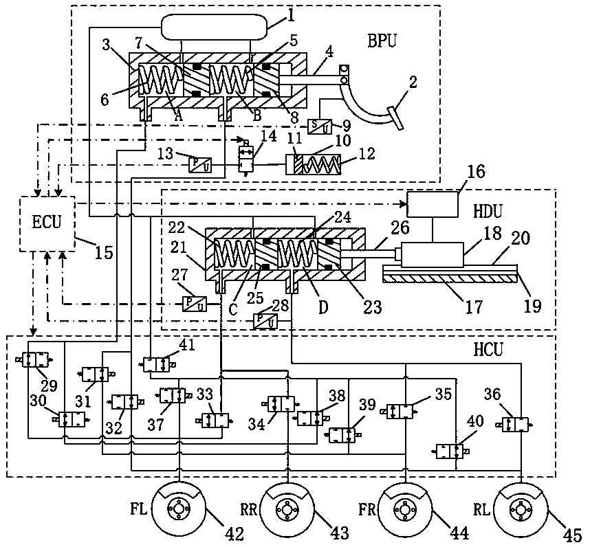
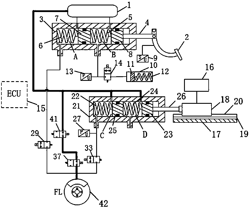
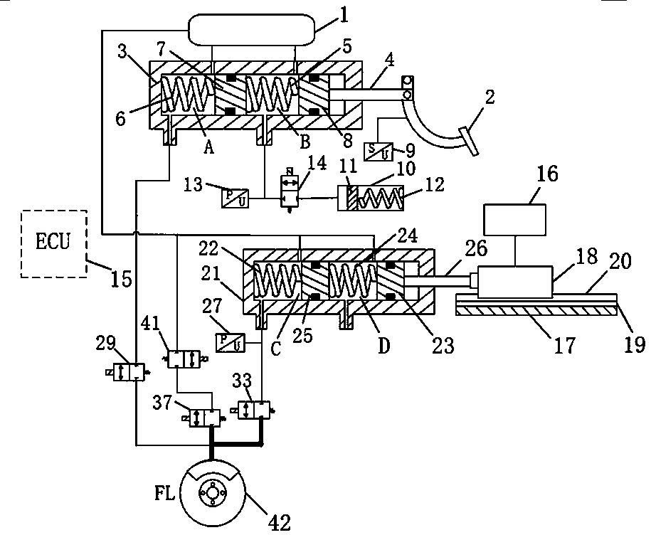
[0027] refer to figure 1 , The present invention is an integrated electronic hydraulic braking system, which is composed of brake pedal unit (BPU), hydraulic drive unit (HDU), electronic control unit (ECU), hydraulic control unit (HCU) and wheel brakes.

[0028]The brake pedal unit (BPU) is composed of a liquid storage tank 1, a brake pedal 2, a first brake master cylinder 3, a pedal connecting rod 4, a brake pedal stroke sensor 9, a brake pedal stroke simulator 10, The first pressure sensor 13 and the first decoupling valve 14 are composed. Wherein, the fluid storage tank 1 is used for storing brake fluid. The outside of the first brake master cylinder 3 is a cylinder body, and the cylinder body is provided with a piston 7 in the front chamber of the first master cylinder and a piston 8 in the rear chamber of the first master cylinder. The piston 8 in the cylinder rear chamber divides the cylinder inner cavity into two chambers, the front chamber A of the first master cylin...


PUM


Abstract

The invention discloses an integrated electronic hydraulic braking system and method, and belongs to the technical field of automobile braking systems. The braking system adopts a mode that a linear motor directly drives a braking master cylinder to control hydraulic pressure of the system, and the linear motor and the braking master cylinder are integrated to serve as a power source of the braking system; under a conventional braking mode, the motion of the linear motor is controlled, so that pressure in a brake wheel cylinder can be quickly and accurately adjusted, high-pressure energy storage devices such as a high-pressure energy accumulator and a hydraulic pump are eliminated, and a mode that the linear motor replaces a rotating motor to be combined with a transmission mechanism is adopted, so that the influence of mechanical friction on the system process is reduced; when the motor fails or the system loses power, braking performance of an automobile can still be realized by a driver stepping on a brake pedal, and thus the reliability of the braking system is ensured; and an anti-lock braking function is integrated to improve the active safety performance of the braking system.

Description

technical field [0001] The invention belongs to the technical field of automobile brake systems, and in particular relates to an electronic hydraulic brake system. Background technique [0002] The development of automobile electrification and intelligence has promoted the development of the brake system in the direction of brake-by-wire, which is not only consistent with the development trend of modern automobiles towards modularization, integration, and mechatronics, but also in line with the new requirements of automobiles for braking systems. need. The brake-by-wire system can independently adjust the hydraulic braking force of the four wheels and realize precise control of the hydraulic braking force. Due to the current demand for intelligent automobiles, automatic driving technologies such as advanced driver assistance systems (ADAS) and automatic emergency braking systems (AEB) require brake-by-wire technology. Therefore, brake-by-wire systems will replace traditiona...

Claims


Application Information

Patent Timeline
Patent Type & Authority Applications(China)
IPC IPC(8): B60T8/34B60T13/14B60T13/74
Inventor 何仁张东
Owner JIANGSU UNIV
Why Eureka
Try Eureka