Oil pump rotor assembly

A rotor and component technology, applied in the field of oil pump rotor component structure, can solve problems such as application limitation, meshing impact, and reduce displacement, and achieve the effects of wide practical value, stable operation, and avoiding oil trapping.

Active Publication Date: 2019-05-10
重庆红宇精密工业集团有限公司
View PDF8 Cites 3 Cited by
  • Summary
  • Abstract
  • Description
  • Claims
  • Application Information

AI Technical Summary

Problems solved by technology

However, there is an insurmountable defect in the oil pump of this structure, that is, the radius of curvature of the transition curve between the tooth top and the tooth side of the inner rotor is very small, causing the curvature radius of the transition curve to change too rapidly to form a bulge or a top cut. , the meshing inner rotor transition curve part is easy to wear and cause meshing impact, causing noise
The traditional method is to repair the drum rib or top cut part of the inner rotor to avoid the wear of the transition curve, but it also destroys the continuity of the meshing of the inner and outer rotors, and vibration and noise will occur when the rotor rotates at high speed
On the other hand, when the tooth top of the inner rotor of the oil pump with the above structure rotates to the tooth root of the outer rotor, a closed cavity is formed to trap oil and cause noise, which is unavoidable in traditional rotor pumps, and the closed cavity will also discharge oil Chamber fluid is input into the oil chamber, reducing displacement and reducing efficiency
The above shortcomings limit the application of traditional rotor pumps in hydraulic systems that pay more and more attention to noise

Method used


Image

  • Oil pump rotor assembly
  • Oil pump rotor assembly
  • Oil pump rotor assembly

Examples


Embodiment 1

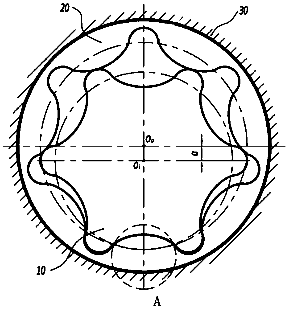
[0025] This embodiment provides an oil pump rotor assembly, including an inner rotor 10 and an outer rotor 20 arranged in a rotor chamber of a casing 30 .

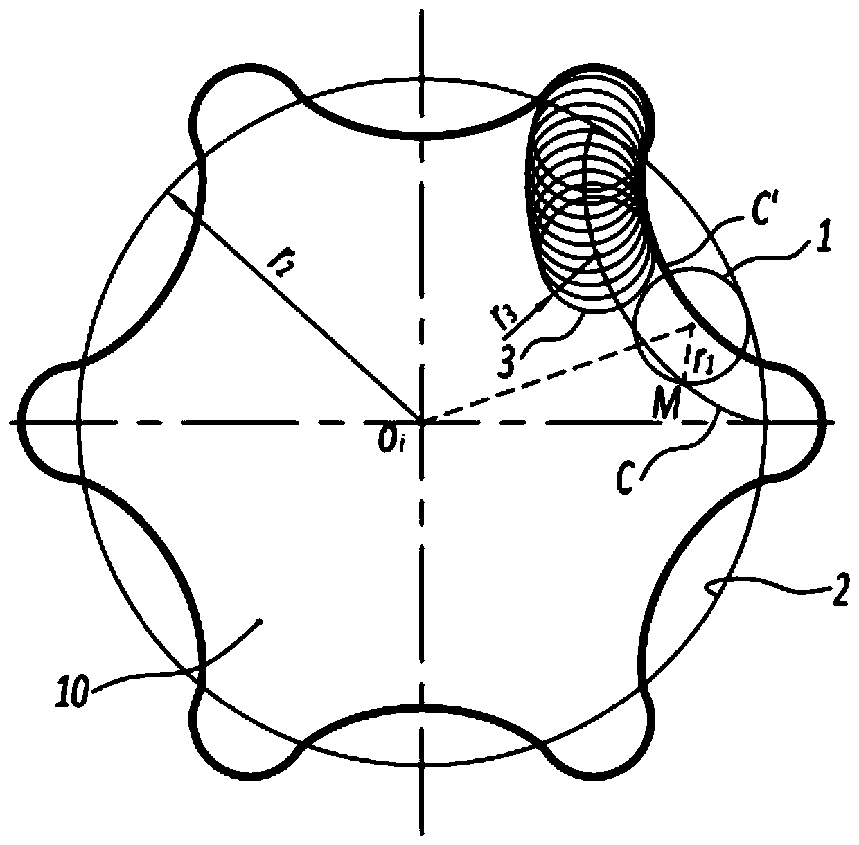
[0026] The tooth profile profile of the inner rotor 10 has a radius r 3 And the envelope curve C' of a set of trajectory circle I3 whose center is on the hypocycloid C. The hypocycloid C is the locus of a fixed point M on the circumference of the rolling circle I1 when the rolling circle I1 is inscribed on the base circle I2 for rolling without slip. The radius of the rolling circle I1 is r 1 . The radius of the base circle I2 is r 2 .

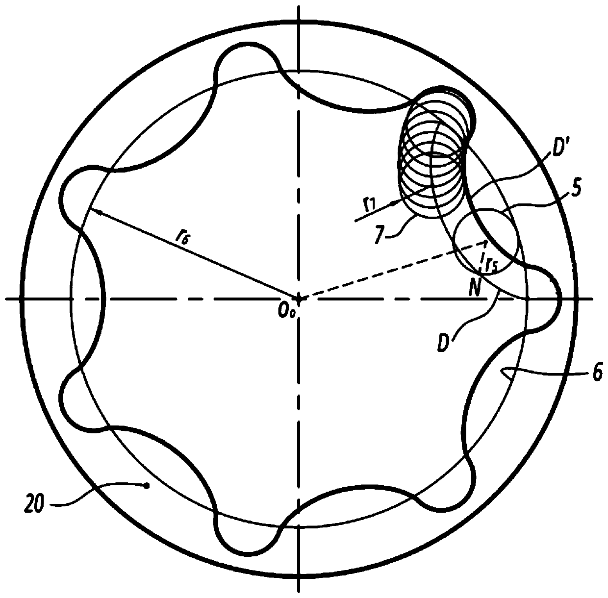
[0027] The tooth profiles of the outer rotor 20 have a radius r 7 And the envelope curve D' of a set of trajectory circle II7 whose center is on the hypocycloid D. The hypocycloid D is the locus of a fixed point N on the circumference of the rolling circle II5 when the rolling circle II5 is inscribed on the base circle II6 for rolling without sliding. The radius r of the spherical I...

Embodiment 2

[0031] This embodiment provides an oil pump rotor assembly, including an inner rotor 10 and an outer rotor 20 arranged in a rotor chamber of a casing 30 .

[0032] see figure 1 , the inner rotor 10 is in conjugate engagement with the outer rotor 20 . The inner rotor 10 has 6 teeth and the outer rotor 20 has 7 teeth. The casing 30 has a suction port for sucking fluid and a discharge port for discharging fluid. The inner rotor 10 and the outer rotor 20 are conjugated in constant ratio transmission. The center of the inner rotor is O i , the center of the outer rotor is O o , the center distance between the inner rotor 10 and the outer rotor 20 is a.

[0033] see figure 2 , the formation process of the tooth profile of the inner rotor 10 is as follows: the rolling circle I1 is inscribed with the fixed base circle I2 and performs pure rolling, and the trajectory of a point M on the rolling circle I1 forms a hypocycloid C. The hypocycloid C is closed, and the hypocycloid C ...


PUM


Abstract

The invention provides an oil pump rotor assembly. The tooth shapes of an inner rotor and an outer rotor in the oil pump rotor assembly are composed of envelope curves of a hypocycloid formed by a fixed connection point on a rolling circle and circular arcs through the mode that the rolling circle purely rolls along a fixed base circle. According to the oil pump rotor assembly, the tooth shapes ofthe inner rotor and the outer rotor are set through appropriate parameters, the appropriate meshing clearance is set, edge bulging and crest cutting of tooth crests of rotors in a traditional rotor pump are avoided, the problems of tooth crest meshing abrasion, vibration, noise, meshing oil-trapping during working of the traditional rotor pump are effectively solved, meanwhile, the displacement of an oil pump is increased, and the efficiency is improved.

Description

technical field [0001] The invention relates to the technical field of hydraulic transmission, in particular to an oil pump rotor assembly structure. Background technique [0002] The traditional rotor pump works in the way of arc and cycloid meshing, including the inner rotor with n (natural number of n≥3) teeth formed by short epicycloid equidistant curve and the inner rotor with n+1 teeth formed by arc. an outer rotor, and a casing formed with a suction port for sucking in fluid and a discharge port for discharging fluid. When the oil pump is working, the meshed oil pump rotor assembly rotates to suck and discharge fluid by changing the volume change formed by the meshed rotor and the housing with the suction port and the discharge port. [0003] The oil pump with the above structure has a simple and compact structure, and is widely used in hydraulic transmission systems, especially lubricating oil pumps on automobile engines and automatic transmission oil pumps mostly a...

Claims


Application Information

Patent Timeline
Patent Type & Authority Applications(China)
IPC IPC(8): F04C15/00F04C2/10F16N13/20
Inventor 杨昌林唐春申小刚杨建
Owner 重庆红宇精密工业集团有限公司
Why Eureka
Try Eureka