Modular DC energy consumption device and control method

An energy-consuming device and a modular technology, which is applied in the direction of load balancing in the DC network, voltage adjustment of the AC network, integration of the power network operating system, etc., can solve problems such as low reliability, power failure, and voltage increase of the DC transmission line. , to achieve good reliability and safety, reduce the difficulty of equipment manufacturing, and reduce the overall cost

Pending Publication Date: 2019-05-10
NR ELECTRIC CO LTD +1
View PDF1 Cites 10 Cited by
  • Summary
  • Abstract
  • Description
  • Claims
  • Application Information

AI Technical Summary

Problems solved by technology

Modular DC energy consumption devices are mainly used in the application scenario of island power supply. If the power generation end is an inertial power source similar to wind power, when the power receiving end fails, because the power cannot be sent out, the energy will be accumulated on the DC side, resulting in the failure of the DC transmission line. The voltage rise will cause harm to the safe operation of the equipment
[0003] The commonly used technical solution in the prior art is to use power semiconductor devices, such as IGBT directly connected in series and a centralized resistance solution. The IGBT valve string is subjected to high voltage, and the concentrated resistance consumes energy. The consistency requirements for opening and closing are extremely high. Once there is inconsistency, some valve sections will be over-pressured and burned. Due to the continuous opening and closing during work, the risk of device damage is high; there are also technical solutions that propose modular solutions, but The solution has the defects of large number of components, high cost, and low reliability, such as the solution proposed in the patent CN102132484B-converter with distributed braking resistors, such as image 3 As shown, the main function of the bridge arm composed of diodes in this scheme is to prevent the capacitor from being discharged directly to the short circuit point when an external short circuit occurs. The one-way conduction characteristic of the diode blocks the path of capacitor discharge. The main defect of this is: ( 1) When charging, the equivalent circuit is the series capacitance of the upper tube of the diode bridge arm, which has a high rate of current change, and a current-limiting reactor needs to be connected in series in the circuit; (2) The number of devices in this scheme is large, including 4 groups of power semiconductors devices, the reliability of power semiconductor devices is relatively low, which makes the failure rate of the whole module higher and the cost is higher
(3) In this solution, a large current flows through the upper tube of the diode bridge arm during energy consumption. Due to the effect of parasitic inductance, there is an overvoltage risk when it is turned off. In practical engineering applications, a clamp absorption circuit needs to be added; (4) When the module fails When bypassing or when maintenance is required, the DC capacitor has no discharge path, and it takes a long time to drop to a safe voltage and cannot be detected; (5) When an external short circuit occurs, it is equivalent to a fault state, and the capacitor cannot be discharged at this time, posing a safety hazard , the most ideal way to deal with it is to quickly discharge the capacitor, so that the capacitor voltage drops below the safe value; in order to overcome the above defects, the present invention provides a solution with low cost and high reliability

Method used


Image

  • Modular DC energy consumption device and control method
  • Modular DC energy consumption device and control method
  • Modular DC energy consumption device and control method

Examples


Embodiment Construction

[0045] The present invention will be further described below in conjunction with accompanying drawing.

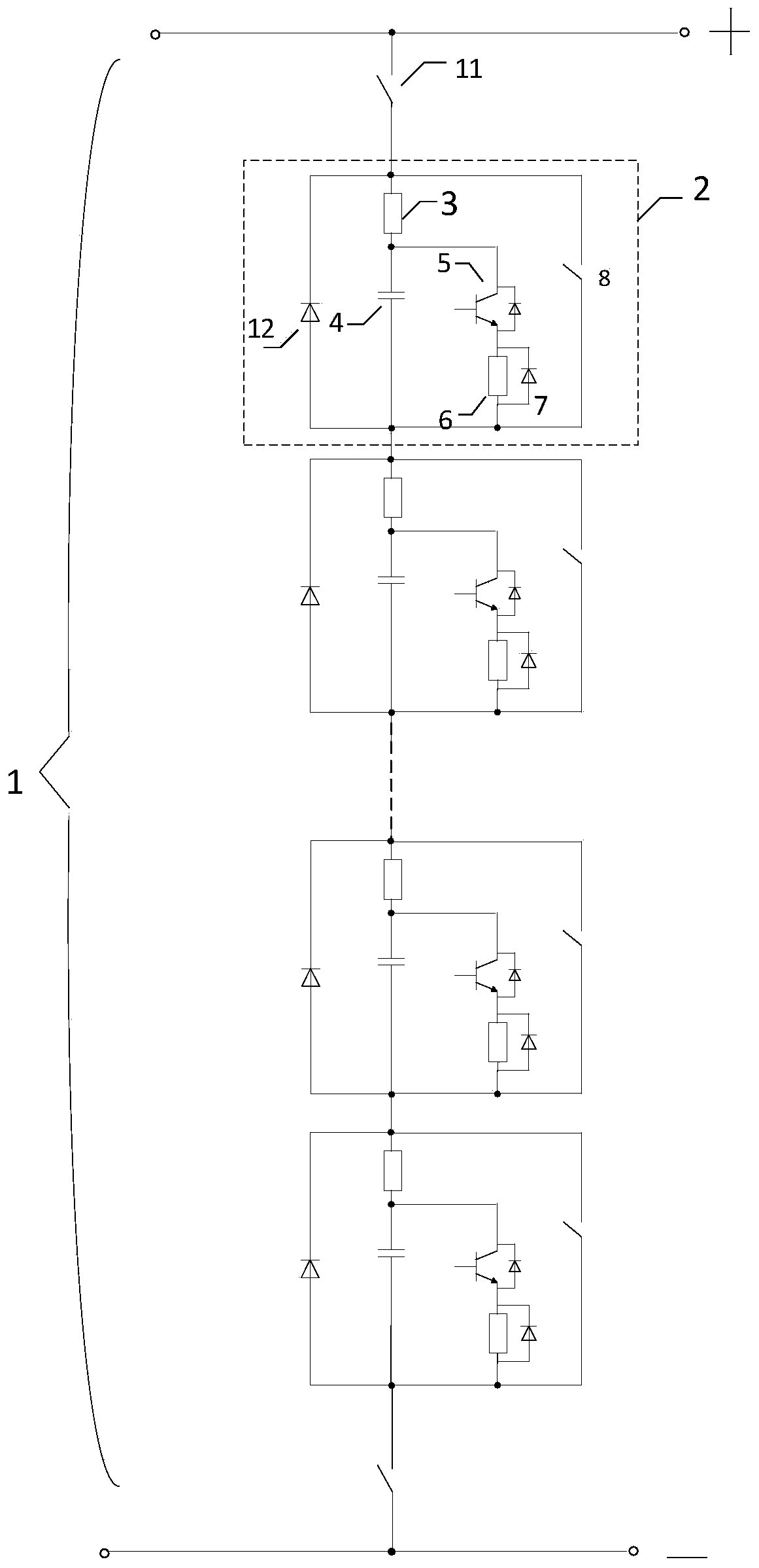
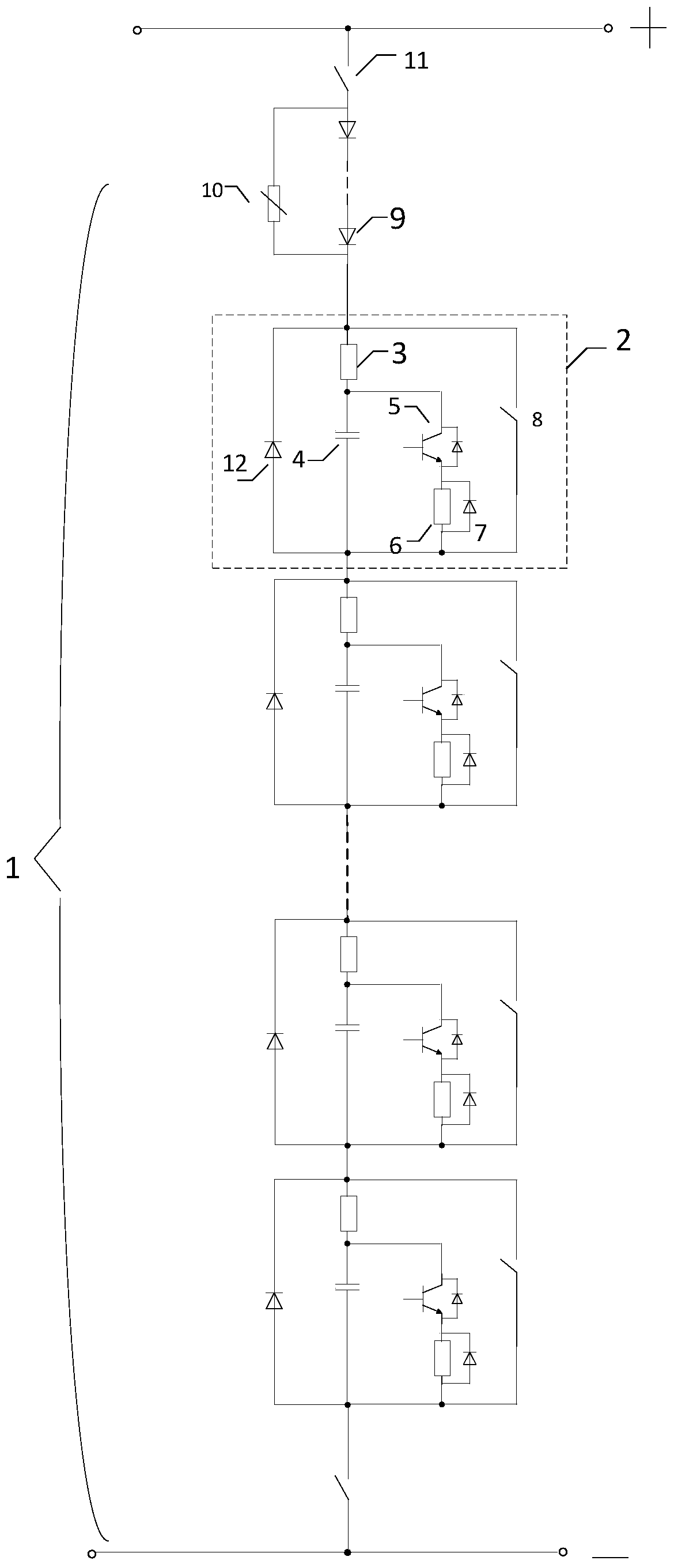
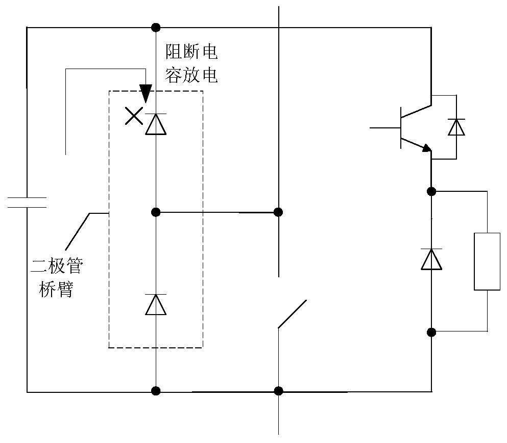
[0046] like figure 1 As shown, the device 1 includes at least two equalizing energy consumption modules 2, and the at least two equalizing energy consuming modules are connected in series in the same direction; the equalizing energy consuming module includes a DC capacitor 4, a current limiting unit 3, Energy consumption branch and bypass switch 8, the DC capacitor is connected in series with the current limiting unit to form a first series unit, and the head end and tail end of the first series unit are used as the head end and tail end of the voltage equalization energy consumption module ; The energy consumption branch is connected in parallel at both ends of the DC capacitor, and the energy consumption branch includes a first power semiconductor device 5 and an energy consumption resistor 6 connected in series; the current limiting unit includes a device with a current...


PUM


Abstract

The invention discloses a modular DC energy consumption device. The device comprises at least two voltage-sharing energy consumption modules, wherein the at least two voltage-sharing energy consumption modules are connected in series in the same direction, each voltage-sharing energy consumption module comprises a DC capacitor, a current-limiting unit, an energy consumption branch and a bypass switch, the DC capacitor and the current-limiting unit are connected in series to form a first series unit, an initial end and a tail end of the first series unit both are used as an initial end and a tail end of the voltage-sharing energy consumption module, the energy consumption branch is connected in parallel with two ends of the DC capacitor, and the bypass switch is connected in parallel with the first series unit. The invention also discloses a control method of the modular DC energy consumption device. When a voltage of a DC circuit is raised, the withdraw of an energy consumption resistor is controlled by controlling a first power semiconductor device so as to stabilize a DC voltage; and when a fault occurs in the voltage-sharing energy consumption module or a DC circuit is circuit-shorted, a discharging current of the capacitor is limited by the current-limiting unit. The device is high in cost performance and high in reliability and is easy to implement.

Description

technical field [0001] The invention belongs to the technical field of high-power electric current conversion, and in particular relates to a modular direct-current energy consumption device and a control method. Background technique [0002] In HVDC power transmission systems, modular DC energy consumers are crucial equipment. Modular DC energy consumption devices are mainly used in the application scenario of island power supply. If the power generation end is an inertial power source similar to wind power, when the power receiving end fails, because the power cannot be sent out, the energy will be accumulated on the DC side, resulting in the failure of the DC transmission line. The voltage rise will cause harm to the safe operation of the equipment. [0003] The commonly used technical solution in the prior art is to use power semiconductor devices, such as IGBT directly connected in series and a centralized resistance solution. The IGBT valve string is subjected to high...

Claims


Application Information

Patent Timeline
Patent Type & Authority Applications(China)
IPC IPC(8): H02J3/14H02J1/14
CPCY02B70/3225Y04S20/222
Inventor 谢晔源曹冬明王宇李海英孙乐
Owner NR ELECTRIC CO LTD
Why Eureka
Try Eureka