[0019] The technical solutions in the embodiments of the present invention will be clearly and completely described below in conjunction with the accompanying drawings in the embodiments of the present invention. Obviously, the described embodiments are only a part of the embodiments of the present invention, rather than all the embodiments. Based on the embodiments of the present invention, all other embodiments obtained by those of ordinary skill in the art without creative work shall fall within the protection scope of the present invention.
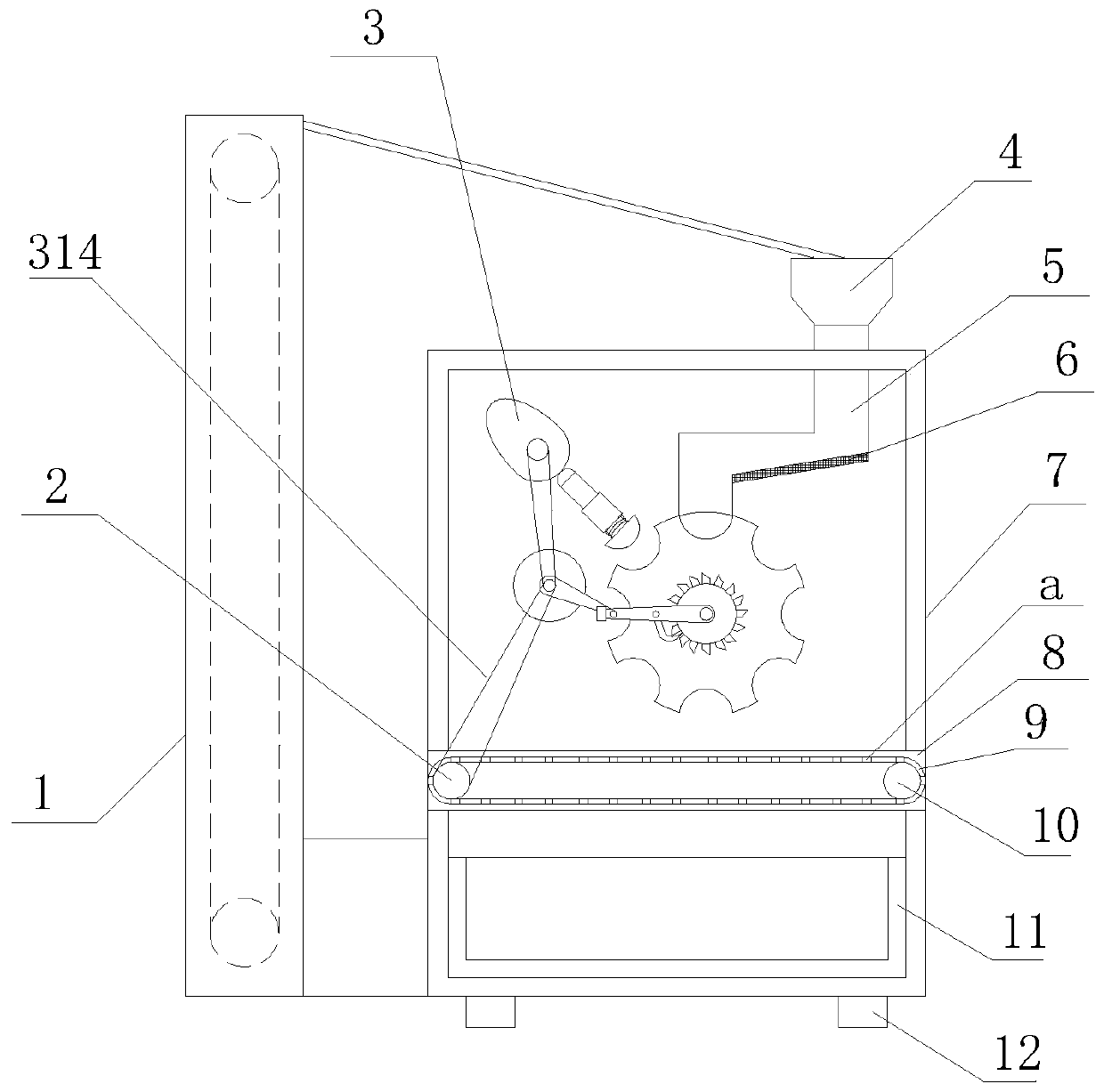
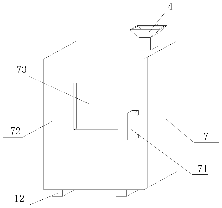
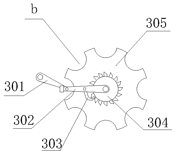
[0020] See Figure 1-4 , The present invention provides a technical solution: a grinding equipment for rough diamond processing, comprising a device main body and a grinding mechanism 3, the device main body including a hoist 1, a driving roller 2, a feeding port 4, a guide channel 5, a screen The plate 6, the box body 7, the mounting frame 8, the transmission belt 9, the driven roller 10, the collecting trough 11 and the feet 12, the feet 12 are arranged on the lower end surface of the box body 7, and the feed opening 4 is opened on the top surface of the box body 7, The inner top surface of the box body 7 is provided with a guide channel 5, and the guide channel 5 is connected with the bottom end of the feeding port 4, the bottom end of the guide channel 5 is provided with a sieve plate 6, and the mounting frame 8 is set in the lower part of the box body 7. The driving roller 2 and the driven roller 10 are both rotatably connected to the inner end surface of the mounting frame 8. The transmission belt 9 is wrapped on the outer surface of the driving roller 2 and the driven roller 10. The transmission belt 9 is uniformly distributed with leak holes a and collecting trough 11 is arranged on the inner bottom end surface of the box body 7, and the hoist 1 is arranged on the left end surface of the box body 7.
[0021] The grinding mechanism 3 is arranged in the upper part of the box body 7. The grinding mechanism 3 includes a connecting rod 301, a swing rod 302, a pawl 303, a ratchet wheel 304, a grinding roller 305, a cam 306, a guide ball 307, a guide rod 308, The guide sleeve 309, the connecting spring 310, the grinding head 311 and the driving machine 312, the grinding roller 305 and the ratchet wheel 304 are coaxially fixed and rotatably connected inside the box body 7, the driving machine 312 is arranged inside the box body 7, and the swing rod 302 Coaxially rotatably connected with the ratchet wheel 304 inside the box body 7, the pawl 303 is rotatably connected to the swing rod 302, the outer end of the connecting rod 301 is rotatably connected to the swing rod 302, and the inner end of the connecting rod 301 is fixed to the output end of the driver 312 , The cam 306 is rotatably connected inside the box body 7, the guide sleeve 309 is arranged inside the box body 7, the guide rod 308 is positioned inside the guide sleeve 309, the guide ball 307 is arranged on the top of the guide rod 308, and the grinding head 311 is arranged on the guide rod 308 At the bottom end, the grinding head 311 is connected to the bottom end of the guide sleeve 309 through the connecting spring 310, the grinding roller 305 is provided with a grinding groove b, the shaft of the cam 306 and the output end of the driving machine 312 are drivingly connected by a transmission belt 313, and the driving roller 2 Through the transmission connection of the synchronous belt 314 and the output end of the driving machine 312, the present invention has excellent structure, reasonable design, simple operation, good grinding effect, high grinding efficiency, high equipment coordination, wide application prospects, and high creativity.
[0022] There are two supporting feet 12, and the two supporting feet 12 are symmetrically arranged on the lower end surface of the box body 7. The front face of the box body 7 is hinged with a box door 72, and the middle position of the box door 72 is provided with a transparent observation window 73, and the front face of the box door 72 A handle 71 is provided at the middle position on the right side. The outer surface of the grinding roller 305 is equidistantly formed with several sets of grinding grooves b. The volume of the grinding grooves b is larger than the volume of the grinding head 311. The pawl 303 is opposite to the ratchet 304. And the connecting shaft of the pawl 303 and the swing rod 302 is covered with a torsion spring, the left end of the box 7 is provided with a discharge port, and the collecting trough 11 of the hoist 1 is located on the lower side of the discharge port, and the screen plate 6 The sieve holes are uniformly distributed, and the density of the sieve holes is the same as the density of the leak hole a, and the sieve plate 6 is arranged at an angle of 5°-15° upwards with the horizontal plane, and the connecting rod 301 is rotationally connected with the swing rod 302 through a pin. .
[0023] When the present invention is working: Put the diamond raw material into the receiving trough of the elevator 1, the elevator 1 puts the diamond raw material into the box 7 from the feeding port 4, and enters the guide channel 5, and the small diamond particles pass through the screen 6 Downward to the drive belt 9, passing through the leak hole a, enters the collection tank 11 for storage. The large diamond magazine rolls into the grinding tank b through the guide channel 5, and runs the driver 312, and the output end of the driver 312 rotates to drive the connection The rod 301 rotates, and the connecting rod 301 drives the pendulum rod 302 to reciprocate. During the clockwise swing of the pendulum rod 302, the pawl 303 and the ratchet 304 do not work. During the counterclockwise swing of the pendulum rod 302, the pawl 303 pushes the ratchet 304 to rotate counterclockwise. , The connecting rod 301 rotates once, and the pendulum rod 302 reciprocates once, which drives the material position in the grinding trough b to correspond to the grinding head 311 to continue feeding, and at the same time, the output end of the driver 312 rotates to drive the cam 306 to rotate, and the cam 306 and the guide The ball 307 works together. When the tip of the guide ball 307 rotates from left to right, the guide ball 307 pushes the guide rod 308 to move to the right inside the guide sleeve 309, and the guide rod 308 pushes the grinding head 311 to move to the right and enters the grinding Inside the grinding groove b, the diamond material is ground, thereby reciprocating to complete the grinding of the diamond. The insufficiently ground diamond material falls on the transmission belt 9, and the driving roller 2 is driven while the driving machine 312 is working. When rotating, the driving roller 2 drives the transmission belt 9 and the driven roller 10 to rotate, and the transmission belt 9 drives the insufficiently ground diamond material to move to the left, enters the receiving trough of the elevator 1 through the discharge port, and returns to the box body 7 The internal cyclic milling solves the problem that traditional diamond milling equipment is generally made by ultrasonic milling. Ultrasonic milling is suitable for small particles of diamond, but the diamond particles are uneven in size and require manual or mechanical equipment for grinding. Manual waste of labor, relatively simple mechanical equipment, small and large particles are milled together, the efficiency is low, and the effect is poor.
[0024] The above shows and describes the basic principles and main features of the present invention and the advantages of the present invention. For those skilled in the art, it is obvious that the present invention is not limited to the details of the above exemplary embodiments, and does not deviate from the spirit or basics of the present invention. In the case of features, the present invention can be implemented in other specific forms. Therefore, from any point of view, the embodiments should be regarded as exemplary and non-limiting. The scope of the present invention is defined by the appended claims rather than the foregoing description, and therefore it is intended to fall within the claims. All changes within the meaning and scope of equivalent elements of are included in the present invention. Any reference signs in the claims should not be regarded as limiting the claims involved.
[0025] Although the embodiments of the present invention have been shown and described, those of ordinary skill in the art can understand that various changes, modifications, and substitutions can be made to these embodiments without departing from the principle and spirit of the present invention. And variations, the scope of the present invention is defined by the appended claims and their equivalents.